Low-pressure casting method and equipment

A low-pressure casting and equipment technology, applied in the field of low-pressure casting, can solve problems such as low yield, shrinkage and porosity of casting structure, and achieve the effects of reducing defects, improving yield, and improving flow control accuracy and pressure control accuracy

Active Publication Date: 2016-06-22
致能科技有限公司
View PDF8 Cites 1 Cited by
  • Summary
  • Abstract
  • Description
  • Claims
  • Application Information

AI Technical Summary

Problems solved by technology

[0004] The yield of the existing low-pressure casting equipment is low, and there are defects such as shrinkage porosity and pores in the casting structure

Method used


Image

  • Low-pressure casting method and equipment
  • Low-pressure casting method and equipment
  • Low-pressure casting method and equipment

Examples


Embodiment 1

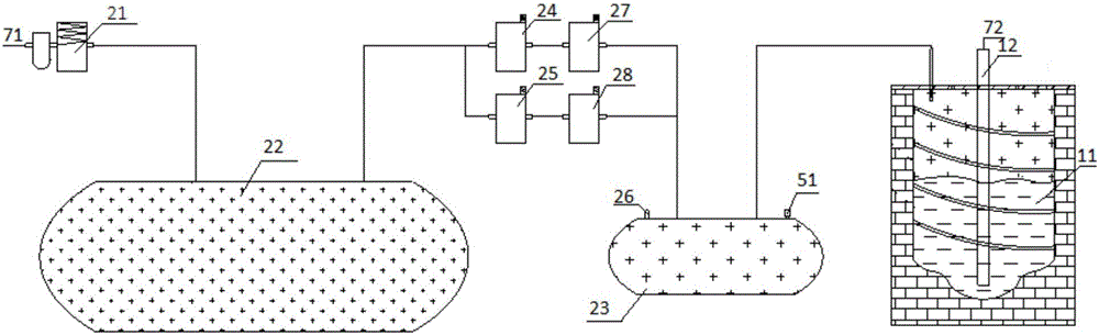
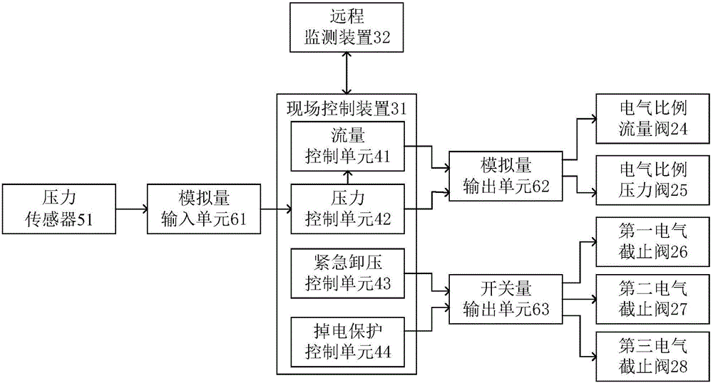
[0050] Such as figure 1 and figure 2 As shown, the low-pressure casting equipment of this embodiment includes a holding furnace 11, a liquid rising pipe 12, a pneumatic circuit and a control system; the liquid rising pipe 12 is arranged in the holding furnace 11 and protrudes from the holding furnace; the air pressure The loop includes a filter decompression valve 21, an air storage tank 22 and a gas pipeline 71; the pneumatic loop also includes a buffer tank 23; the control valve includes an electrical proportional pressure valve 25 and an electrical proportional flow valve 24; the electrical proportional pressure valve 25 is respectively It is connected with the gas storage tank 22 and the buffer tank 23; the electric proportional flow valve 24 is connected with the gas storage tank 22 and the buffer tank 23 respectively; the buffer tank 22 is also connected with the holding furnace 11; the control system includes on-site The control device 31, the on-site control device i...

Embodiment 2

[0087] Such as figure 1 and figure 2 As shown, the low-pressure casting method of this embodiment is based on the low-pressure casting equipment described in Example 1, and includes the following steps:

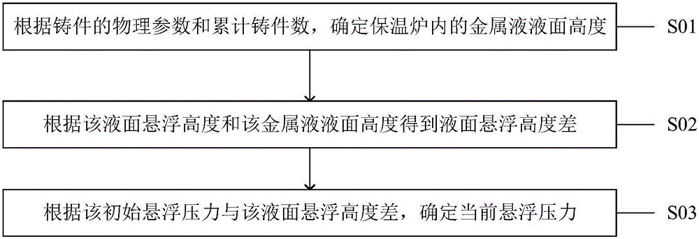
[0088] The on-site control device generates a flow control command and sends it to the electric proportional flow valve according to the low-pressure casting process parameters, and generates a pressure control command and sends it to the electric proportional pressure valve; the low-pressure casting process parameters include liquid level suspension height, initial suspension pressure, filling velocity, filling pressure, crusting pressure, crusting velocity, crusting time, crystallization pressure, crystallization velocity, or crystallization time; correspondingly,

[0089] The electric proportional pressure valve controls the pressure of the compressed gas in the buffer tank in the suspension step, filling step, crusting step or crystallization step according to the press...


PUM


Abstract

The invention belongs to the technical field of low-pressure casting, and particularly relates to a low-pressure casting method and equipment. The low-pressure casting equipment comprises a heat preserving furnace, a riser tube, a pneumatic circuit and a control system, wherein the pneumatic circuit comprises a gas storage tank and a control valve, and further comprises a buffer tank; the control valve comprises an electro-pneumatic proportional pressure valve and an electro-pneumatic proportional flow valve; the electro-pneumatic proportional pressure valve is connected with the gas storage tank and the buffer tank; the electro-pneumatic proportional flow valve is connected with the gas storage tank and the buffer tank; the buffer tank is further connected with the heat preserving furnace; the control system comprises an on-site control device; the on-site control device comprises a pressure control unit and a flow control unit; the pressure control unit is connected with the electro-pneumatic proportional pressure valve; the flow control unit is connected with the electro-pneumatic proportional flow valve. The low-pressure casting method and equipment have the advantage that pressure of compressed gas can be adjusted precisely in a casting process, so as to reduce defects of a casting structure and improve yield.

Description

technical field [0001] The invention belongs to the technical field of low-pressure casting, and in particular relates to a low-pressure casting method and equipment. Background technique [0002] Low-pressure casting is a casting method between pressure casting and gravity casting. It has the characteristics of smooth filling of molten metal and compact structure of castings. A complete low-pressure casting process cycle usually includes process steps such as mold releasing step, liquid raising step, mold filling step, crusting step, crystallization step, suspension step, and mold unloading step. [0003] Low pressure casting equipment usually includes holding furnace, riser, mold, air pressure circuit and control system. The liquid riser is arranged in the holding furnace, and protrudes from the holding furnace into the mold cavity. The control system is used to realize the process control of various requirements in low pressure casting production. The air pressure circ...

Claims


Application Information

Patent Timeline
Patent Type & Authority Applications(China)
IPC IPC(8): B22D18/04B22D18/08
CPCB22D18/04B22D18/08
Inventor 章凯金文章刘仙军刘洋
Owner 致能科技有限公司
Why Eureka
Try Eureka