Working link and valve port independent control type multi-way valve and engineering machinery
A working coupling and working oil port technology, applied in the hydraulic field, can solve the problems of energy waste, complex control system, and high sensor cost, and achieve the effects of increasing the degree of control freedom, high flow control accuracy, and simple structure.
- Summary
- Abstract
- Description
- Claims
- Application Information
AI Technical Summary
Problems solved by technology
Method used
Image
Examples
Embodiment 1
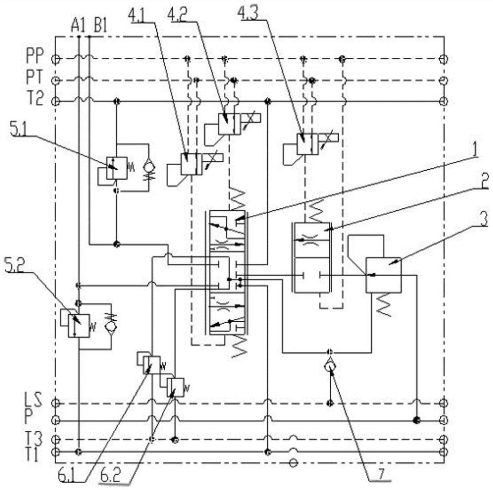
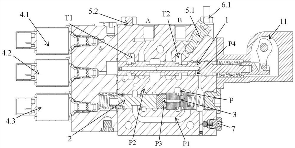
[0047] Such as figure 2 with image 3 As shown, a working couplet includes a valve body, a main valve core 1, a main valve core 2 and a pilot control module. The valve body is provided with an oil supply port P, a working oil port A, and a working oil port B. The main valve Core one 1 can be movably set in the valve body, and is used to control the oil outlet of working oil port A and the oil return of working oil port B, or control the oil outlet of working oil port B and the oil return of working oil port A, and the main valve core two 2 It is movably arranged in the valve body and is used to control the amount of oil entering the working union from the oil supply port P. The pilot control module includes a first pilot control unit for controlling the movement of the main spool one 1 and for controlling the main Second pilot control unit for spool two 2 movement.
[0048] Specifically, the valve body is provided with an oil return port T1, an oil return port T2, an oil su...
Embodiment 2
[0059] Such as Figure 4 As shown, the above working union also includes an electronically controlled LS overflow valve 9, the inlet of the electronically controlled LS overflow valve 9 is connected to the load feedback oil passage, the first load sensitive oil passage or the second load sensitive oil passage, and the valve body is provided with There are a first control selection oil circuit 8.1, a second control selection oil circuit 8.2 and a third control selection oil circuit 8.3, the first control selection oil circuit 8.1 is used to connect the inlet of the electronically controlled LS relief valve 9 with the first load sensitive oil circuit The second control selection oil circuit 8.2 is used to connect the inlet of the electronically controlled LS relief valve 9 with the second load sensitive oil circuit, and the third control selection oil circuit 8.3 is used to connect the inlet of the electronically controlled LS relief valve 9 with the load A check valve 7 is arra...
Embodiment 3
[0061] Such as Figure 5 As shown, the first pilot control unit includes a first electric proportional reversing valve 10.1, the first pilot control oil circuit and the second pilot control oil circuit are drawn from the two outlets of the first electric proportional reversing valve 10.1 respectively; the second pilot The control unit includes the second electric proportional reversing valve 10.2, the third pilot control oil circuit leads from the outlet of the second electric proportional reversing valve 10.2, and the above working couple also includes a control handle and a control signal for receiving the control handle through the CAN bus controller, the controller calculates the displacement of main spool one 1 and / or main spool two 2 according to the control signal, and passes through the corresponding first electric proportional reversing valve 10.1 and / or second electric proportional reversing valve 10.2 Control the movement of main spool one 1 and / or main spool two 2....
PUM
 Abstract
Description
Claims
Application Information
 - R&D
- Intellectual Property
- Life Sciences
- Materials
- Tech Scout
- Unparalleled Data Quality
- Higher Quality Content
- 60% Fewer Hallucinations
Browse by: Latest US Patents, China's latest patents, Technical Efficacy Thesaurus, Application Domain, Technology Topic, Popular Technical Reports.
© 2025 PatSnap. All rights reserved.Legal|Privacy policy|Modern Slavery Act Transparency Statement|Sitemap|About US| Contact US: help@patsnap.com


