
System state monitoring reset circuit

A technology of system state and reset circuit, which is applied in the direction of hardware monitoring, data reset device, and response error generation, etc. It can solve the problems of unfavorable product miniaturization, large resource occupation, and high product cost pressure, so as to facilitate wide application and occupy The effect of less resources and improved accuracy

Pending Publication Date: 2022-07-01
CHINA AUTOMOTIVE INNOVATION CORP
View PDF8 Cites 0 Cited by
  • Summary
  • Abstract
  • Description
  • Claims
  • Application Information

AI Technical Summary

Problems solved by technology

[0005] (1) The cost is high, especially in the current environment where the chip supply chain is tense and chip prices are generally rising, the use of watchdog chips puts great pressure on the cost of products;
[0006] (2) Large volume, integrated chip packaging, generally large volume, difficult to arrange on the circuit board, not conducive to product miniaturization, and inflexible layout;
[0007] (3) The control is complicated. Generally, the watchdog chip needs to be driven by communication, which occupies MCU hardware resources and has relatively high timing requirements.
[0008] Therefore, there is a need for an improved technical solution to solve the problems of complex control, large resource occupation, high cost and inflexible layout caused by the use of watchdog chips to monitor and reset MCUs in the prior art

Method used


Image

  • System state monitoring reset circuit
  • System state monitoring reset circuit
  • System state monitoring reset circuit

Examples


Embodiment Construction

[0027] The technical solutions in the embodiments of the present application will be clearly and completely described below with reference to the drawings in the embodiments of the present application. Obviously, the described embodiments are only a part of the embodiments of the present application, but not all of the embodiments. Based on the embodiments in the present application, all other embodiments obtained by those of ordinary skill in the art without creative work shall fall within the protection scope of the present application.

[0028] It should be noted that the terms "first", "second", etc. in the description and claims of the present application and the above drawings are used to distinguish similar objects, and are not necessarily used to describe a specific sequence or sequence. It is to be understood that data so used may be interchanged under appropriate circumstances so that the embodiments of the application described herein can be practiced in sequences ot...


PUM


Abstract

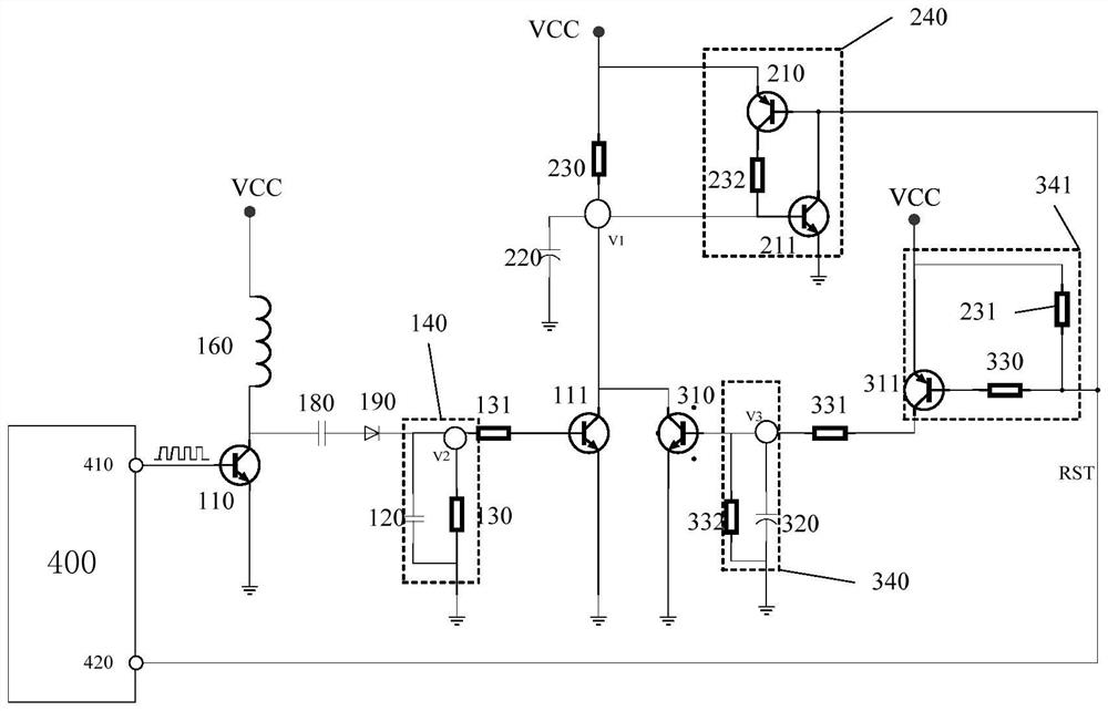
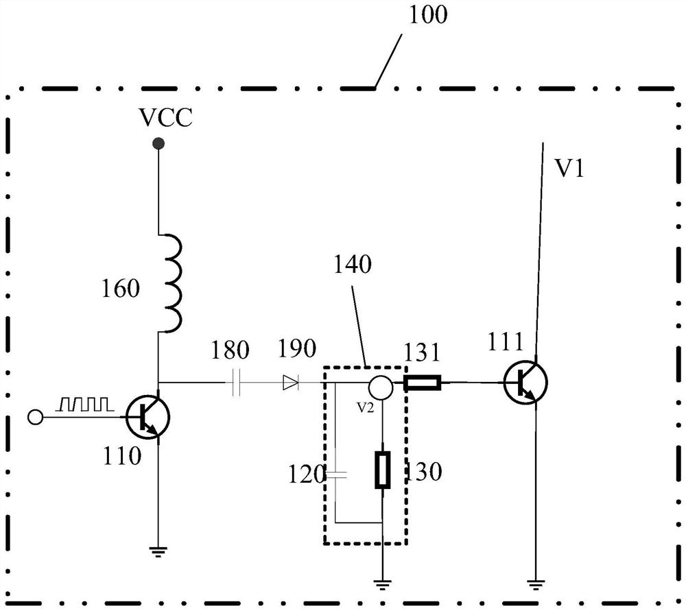
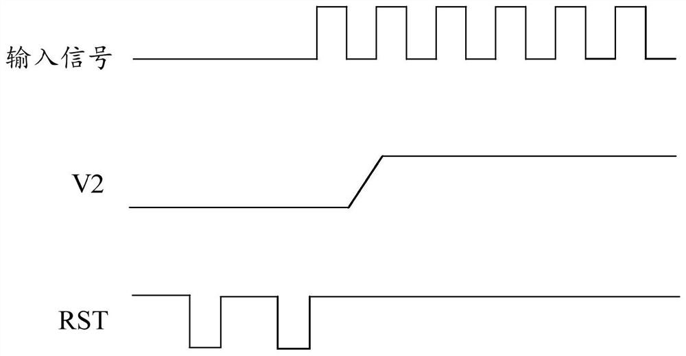
The invention discloses a system state monitoring reset circuit. The circuit comprises a monitoring circuit, a reset signal generation circuit and a reset signal recovery circuit, the input end of the monitoring circuit is used for being connected with a micro-control unit to be monitored, and the output end of the monitoring circuit is connected with the reset signal generation circuit and the reset signal recovery circuit in series. The reset signal generation circuit is connected in parallel with the reset signal recovery circuit; the monitoring circuit is used for controlling the reset signal generation circuit to output a first reset signal in response to a standard electric signal which is sent by the micro-control unit to be monitored and represents that the system state is normal, and controlling the reset signal generation circuit to output a second reset signal in response to an abnormal electric signal which is sent by the micro-control unit to be monitored and represents that the system state is abnormal. And controlling the reset signal generation circuit and the reset signal recovery circuit to output a second reset signal. By using the technical scheme provided by the invention, the monitoring reset of the micro-control unit to be monitored can be realized, the monitoring reset accuracy is improved, the layout is simple, the occupied resources are few, and the wide application is facilitated.

Description

technical field [0001] The present application relates to the technical field of automotive electronic control, in particular to a system state monitoring reset circuit. Background technique [0002] Existing automotive electronic products are easily affected by the external environment, resulting in poor performance of electronic products, such as program running away, program falling into an infinite loop, register bit mutation crash, etc., resulting in the system unable to continue to work normally, making the entire system into a stagnant state. [0003] In the prior art, a watchdog chip is often used to monitor the working state of the system. The watchdog chip is essentially a timer circuit, which generally consists of power supply, input and output. The input is called feeding the dog, and the output is connected to The reset terminal of the Microcontroller Unit (MCU for short). The function of the watchdog is to regularly check the operation of the microcontroller u...

Claims


Application Information

Patent Timeline
Patent Type & Authority Applications(China)
IPC IPC(8): G06F1/24G06F11/07G06F11/30
CPCG06F1/24G06F11/0757G06F11/3003G06F11/3055
Inventor 王志伟汪冬亮张东方黄美娟王君张杰
Owner CHINA AUTOMOTIVE INNOVATION CORP
Learn More