Rainwater recycling fire pool

A technology for fire-fighting pools and rainwater, which is applied in general water supply saving, configuration of water-supply pools, water conservation, etc. It can solve problems such as inability to accurately understand the water volume of fire-fighting pools, poor ability to collect rainwater, and delay the timing of fire extinguishing, so as to increase rainwater collection Effects of Area, Prevention of Emergency, Avoidance of Harm

Inactive Publication Date: 2018-04-17
HEFEI HONGRUN ENVIRONMENTAL PROTECTION TECHCO
0 Cites 0 Cited by

AI-Extracted Technical Summary

Problems solved by technology

[0003] At present, most of the fire pools used are open-air, which will cause a lot of debris to fall into the fire pool. In emergency use, the water pipe may be blocked and the timing of fire extinguishing w...

Method used

Described fire-fighting pool 1 inner wall lays white ceramic tile, improves the firm structure of fire-fighting pool 1, and white ceramic tile is convenient for firefighters to see the inner wall situation clearly simultaneously, and targeted cleaning reduces the labor intensity of firefighters.
[0023] The buoyant ball 11 is made of red foam and has a hollow structure, and the...

Abstract

The invention discloses a rainwater recycling fire pool, which comprises a fire pool, a protecting tank, a hydraulic cylinder, a piston push rod, a lower box hinge, a water storage tank, a water inlet, a supporting cover, a funnel, a box side hinge, a floating ball, a supporting rod, a connecting pipe, a draining pipe, a filtering layer and a disinfecting layer; the side face of the fire pool is provided with the protecting box, and the left upper part of the inside of the protecting box is provided with the hydraulic cylinder; the inner part of the hydraulic cylinder is provided with the piston push rod, and the upper part of the piston push rod is provided with the water storage tank; the middle part of the lower part of the water storage tank is welded with the lower box hinge, the water storage box is connected with the piston push rod through the lower box hinge; the right side face of the water storage box is welded with the box side hinge, and the water storage box is connectedwith one side of the supporting cover through the box side hinge; one side of the supporting cover is in threaded connection to the upper part of the side face of the fire pool, and the other side ofthe supporting cover is in threaded connection with the funnel; a water inlet is arranged at the upper part of the left side face of the fire pool.

Application Domain

General water supply conservationWater supply tanks +2

Technology Topic

PistonWater storage tank +3

Image

  • Rainwater recycling fire pool
  • Rainwater recycling fire pool
  • Rainwater recycling fire pool

Examples

  • Experimental program(1)

Example Embodiment

[0018] The technical solutions in the embodiments of the present invention will be clearly and completely described below in conjunction with the accompanying drawings in the embodiments of the present invention. Obviously, the described embodiments are only a part of the embodiments of the present invention, rather than all the embodiments. Based on the embodiments of the present invention, all other embodiments obtained by those of ordinary skill in the art without creative work shall fall within the protection scope of the present invention.
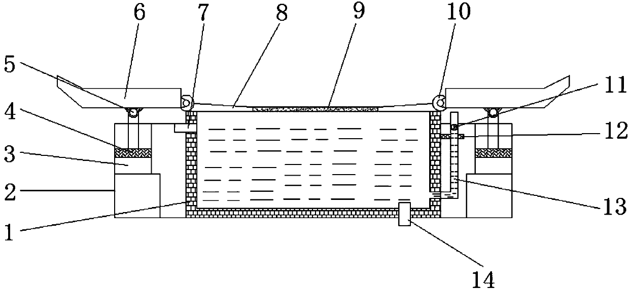
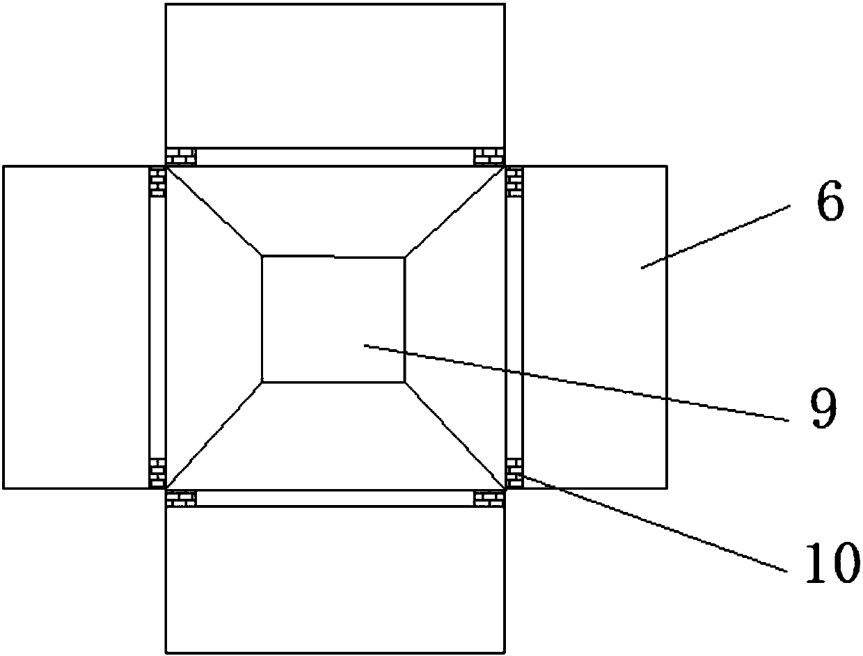
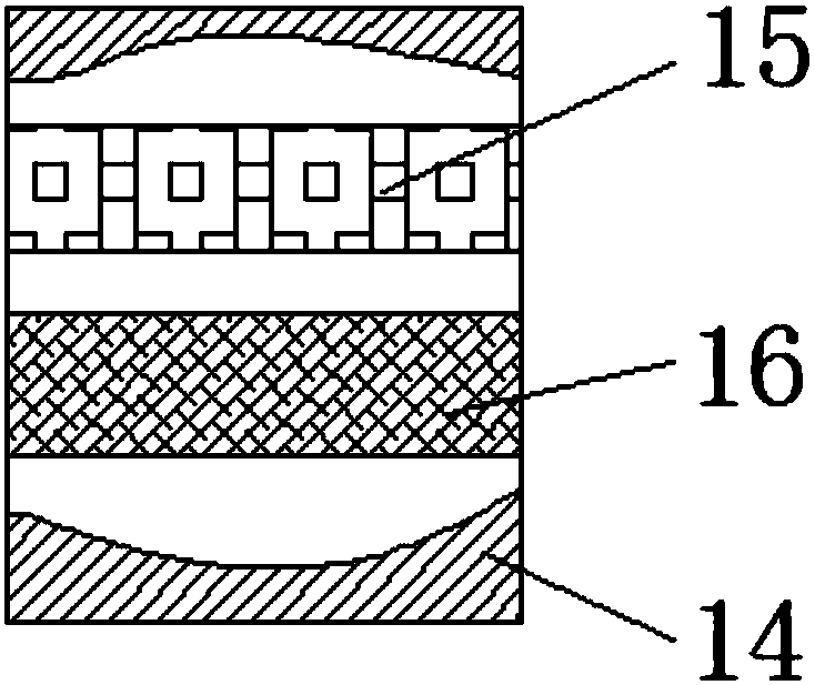
[0019] See Figure 1~3 In the embodiment of the present invention, a rainwater recycling fire-fighting pool includes a fire-fighting pool 1, a protection box 2, a hydraulic cylinder 3, a piston push rod 4, a hinge under the box 5, a water storage tank 6, a water inlet 7, a support cover 8, The funnel 9, the box side hinge 10, the floating ball 11, the support rod 12, the connecting pipe 13, the drain pipe 14, the filter layer 15 and the disinfection layer 16. The side of the fire fighting pool 1 is provided with a protective box 2, and the protective box 2 A hydraulic cylinder 3 is provided on the upper left side of the inner side, and a piston push rod 4 is provided inside the hydraulic cylinder 3, and a water storage tank 6 is provided above the piston push rod 4. The lower middle position of the water storage tank 6 is welded with a lower hinge 5 and a water storage tank 6 The bottom hinge 5 is connected with the piston push rod 4, the right side of the water storage tank 6 is welded with a tank side hinge 10, the water storage tank 6 is connected to one side of the support cover 8 through the tank side hinge 10, and the support cover 8 passes through the side Threaded connection to the upper side of the fire pool 1, and the other side of the support cover 8 is threaded to the funnel 9. When working in rainy days, the hydraulic press under the hydraulic cylinder 3 is started, and the piston push rod 4 pushes the water storage tank 6 filled with rainwater upwards. Since the right side of the water storage tank 6 is fixed, the water storage tank 6 is inclined to the right, and the rainwater in the water storage tank 6 is introduced to the supporting cover 8 and simply filtered through the funnel 9 into the fire fighting pool 1.
[0020] The water inlet 7 is installed on the upper left side of the fire fighting pool 1. A connecting pipe 13 is arranged on the right side of the fire fighting pool 1, and a floating ball 11 is arranged inside the connecting pipe 13, and the right side of the fire fighting pool 1 is arranged There is a support rod 12, and the protection connecting pipe 13 is in a vertical position. When working, the floating body ball 11 can show the liquid level in the fire fighting pool 1. When the floating body ball 11 is too low, it reminds firefighters that the water inlet 7 The water is pumped into the fire fighting pool 1 to avoid insufficient water in the fire fighting pool 1 in an emergency situation. A drainage pipe 14 is provided at the lower right corner of the fire fighting pool 1. The drainage pipe 14 is provided with a filter layer 15 and a disinfection layer 16 inside. 15 is set above the disinfection layer 16. The disinfection layer 16 is filled with potassium permanganate particles. During fire fighting, the filter layer 15 filters out debris in the water to prevent the water pipe from being blocked. The disinfection layer 16 ensures that the moisture is harmless and avoids spraying during fire fighting. On the human body, it is harmful to the human body.
[0021] White tiles are laid on the inner wall of the fire-fighting pool 1 to improve the firm structure of the fire-fighting pool 1. At the same time, the white tiles are convenient for firefighters to see the condition of the inner wall and clean them in a targeted manner, thereby reducing the labor intensity of firefighters.
[0022] The connecting pipe 13 is made of transparent plastic, and the connecting pipe 13 is provided with a scale line. The bottom of the connecting pipe 13 is connected to the fire fighting pool 1, which can display the water level in the fire fighting pool, and the height of the water level can be displayed by the scale line, which is convenient Calculate the amount of water in the fire pool 1.
[0023] The floating body small ball 11 is made of red foamed plastic and has a hollow structure. The red small ball is suspended in the connecting pipe 13 to facilitate observation of the water level and remind firefighters to pay attention to observation.
[0024] The filter layer 15 is filled with activated carbon particles, which can filter out debris with a large diameter in the water, and avoid blocking the water pipe during fire fighting and delaying the time of fire fighting.
[0025] There are four groups of the water storage tank 6 and the protection tank 2, which are distributed around the fire-fighting pool 1 to increase the area for collecting rainwater in rainy days and improve the efficiency of rainwater collection.
[0026] The working principle of the present invention is: when the present invention is used, the hydraulic press under the hydraulic cylinder 3 is started when working on rainy days, and the piston push rod 4 pushes the water storage tank 6 filled with rainwater to move upwards. Since the right side of the water storage tank 6 is fixed, The water storage tank 6 is tilted to the right, the rainwater in the water storage tank 6 is led to the support cover 8, and is simply filtered through the funnel 9 and then enters the fire fighting pool 1. During fire fighting, the filter layer 15 filters out the debris in the water, and the floating ball 11 can display Out of the liquid level in the fire fighting pool 1, when the floating ball 11 is too low, remind firefighters to pump water from the water inlet 7 into the fire fighting pool 1, to avoid insufficient water in the fire pool 1 in an emergency, and fire fighting At the time, the filter layer 15 filters out the debris in the water to prevent the water pipe from being blocked, and the disinfection layer 16 ensures that the moisture is harmless and avoids spraying on the human body during fire fighting and causing harm to the human body.
[0027] For those skilled in the art, it is obvious that the present invention is not limited to the details of the foregoing exemplary embodiments, and the present invention can be implemented in other specific forms without departing from the spirit or basic characteristics of the present invention. Therefore, from any point of view, the embodiments should be regarded as exemplary and non-limiting. The scope of the present invention is defined by the appended claims rather than the foregoing description, and therefore it is intended to fall within the claims. All changes within the meaning and scope of equivalent elements of are included in the present invention. Any reference signs in the claims should not be regarded as limiting the claims involved.

PUM

no PUM

Description & Claims & Application Information

We can also present the details of the Description, Claims and Application information to help users get a comprehensive understanding of the technical details of the patent, such as background art, summary of invention, brief description of drawings, description of embodiments, and other original content. On the other hand, users can also determine the specific scope of protection of the technology through the list of claims; as well as understand the changes in the life cycle of the technology with the presentation of the patent timeline. Login to view more.

Similar technology patents

Breeding method for breeding rabbits

InactiveCN105961333Anovel ideaunique method
Owner:广西田东隆祥兔业有限公司

Classification and recommendation of technical efficacy words

  • novel idea

Oil spilling alarm buoy device

ActiveCN101774421Anovel ideaunique structure
Owner:北京奥佳科技发展有限公司

Cloth bag dust collector

Owner:盐城智能终端产业园区开发运营有限公司

Ladle nozzle casting combined drainage plug

Owner:马鞍山中冶钢铁冶金高新技术有限公司 +1
Why Eureka
Try Eureka