Image correction device, image correction method, and projection device

A technology of image correction and projection equipment, which is applied in the field of projection display, can solve the problems of beam crosstalk, affect the 3D experience of movie viewers, and cannot be automated, so as to improve the phenomenon of beam crosstalk, improve the viewing experience, and realize the effect of automatic correction

Inactive Publication Date: 2018-04-17
北京铂石空间科技有限公司
View PDF5 Cites 4 Cited by
  • Summary
  • Abstract
  • Description
  • Claims
  • Application Information

AI Technical Summary

Problems solved by technology

However, a kind of stereoscopic display device which is very popular in theaters is still in the stage of manual adjustment and correction. The stereoscopic display device includes traditional three-light path and traditional two-light path stereoscopic display devices. difficult to debug
[0003] Usually, most automated theaters only have one projectionist, so it is difficult to detect all the equipment every day. It is not discovered until the equipment has serious beam crosstalk, which seriously affects the 3D experience of moviegoers.
At present, these devices cannot be automated and need to be operated manually, resulting in inconvenient management and low efficiency.

Method used


Image

  • Image correction device, image correction method, and projection device
  • Image correction device, image correction method, and projection device
  • Image correction device, image correction method, and projection device

Examples


Embodiment Construction

[0051]Example embodiments will now be described more fully with reference to the accompanying drawings. Example embodiments may, however, be embodied in many forms and should not be construed as limited to the examples set forth herein; rather, these embodiments are provided so that this disclosure will be thorough and complete and will fully convey the concept of example embodiments to those skilled in the art. The described features, structures, or characteristics may be combined in any suitable manner in one or more embodiments. In the following description, numerous specific details are provided in order to give a thorough understanding of embodiments of the present disclosure. However, those skilled in the art will appreciate that the technical solutions of the present disclosure may be practiced without one or more of the specific details being omitted, or other methods, components, devices, steps, etc. may be adopted. In other instances, well-known technical solutions...


PUM


Abstract

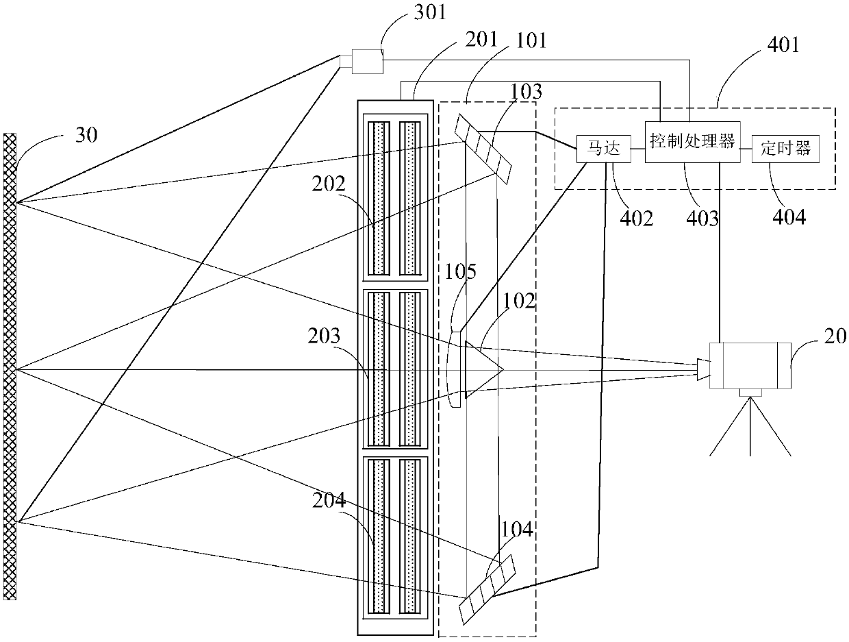
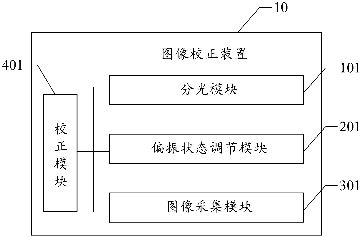
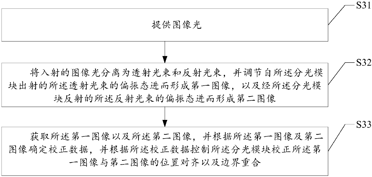
The disclosure, which relates to the field of the projection display technology, provides an image correction device, an image correction method, and a projection device. The image correction device is composed of a light splitting module, a polarization state adjustment module, an image acquisition module, and a correction module. The light splitting module is used for splitting incident image light into a transmission beam and a reflection beam; the polarization state adjustment module is used for adjusting the polarization state of the transmission beam to form a first image and the polarization state of the reflection beam to form a second image; the image acquisition module is used for obtaining the first image and the second image; and the correction module is used for determining correction data based on the first image and the second image and controlling the light splitting module to correct the first image and the second image for position alignment and boundary overlapping based on the correction data. On the one hand, the image is obtained accurately and image correction is realized based on the image position, so that the light beam crosstalk phenomenon is improved andthe watching experience is enhanced; and on the other hand, automatic correction is realized and the manual operation is removed, so that the operating costs are lowered.

Description

technical field [0001] The present disclosure relates to the technical field of projection display, and in particular, to an image correction device, an image correction method, and projection equipment. Background technique [0002] With the development of film projection technology, automation has been extended to most equipment including control and monitoring equipment, and even the action of switching field lights according to projection requirements has been automatically controlled. However, a kind of stereoscopic display device which is very popular in theaters is still in the stage of manual adjustment and correction. The stereoscopic display device includes traditional three-light path and traditional two-light path stereoscopic display devices. Difficult to debug. [0003] Usually, most automated theaters only have one projectionist, so it is difficult to detect all the equipment every day. It is not discovered until the equipment has serious beam crosstalk, whic...

Claims


Application Information

Patent Timeline
Patent Type & Authority Applications(China)
IPC IPC(8): H04N9/31
CPCH04N9/3167H04N9/3179
Inventor 刘贵芹
Owner 北京铂石空间科技有限公司
Why Eureka
Try Eureka