Cabinet mounting plate sliding rail
A technology of mounting plate and slide rail, applied in the field of cabinet spare parts, can solve the problems of alignment of mounting holes, difficult installation, insufficient fixing strength, etc., and achieve the effect of convenient installation and high support strength
- Summary
- Abstract
- Description
- Claims
- Application Information
AI Technical Summary
Problems solved by technology
Method used
Image
Examples
Embodiment 1
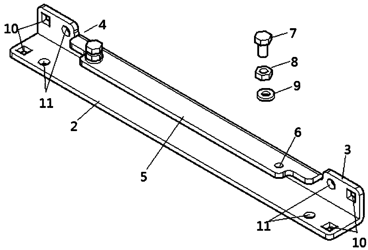
[0026] Such as figure 1 The first shown embodiment is a slide rail for a cabinet mounting plate. The slide rail includes a first track plate 2 and a second track plate 3 perpendicular to each other. The first track plate 2 or the second track plate 3 passes through the installation structure and the cabinet. The column is installed and connected. A concave rectangular groove 4 is provided in the middle of the top of the second track plate 3. The bottom of the rectangular groove 4 is connected with a splint 5 that protrudes to one side and is perpendicular to the second track plate 3. The splint 5 Located on the same side of the second track plate 3 as the first track plate 2, two ends of the splint 5 are respectively provided with a screw hole A6, and a fastening bolt A7 is screwed into the screw hole A6.
[0027] The width of the first track plate 2 is greater than the width of the second track plate 3 .
[0028] Both ends of the first track plate 2 and the second track plat...
Embodiment 2
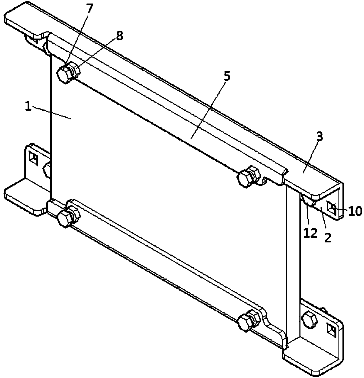
[0030] Such as figure 2 The second embodiment shown is a slide rail for a cabinet mounting plate. The slide rail includes a first track plate 2 and a second track plate 3 that are perpendicular to each other. The first track plate 2 is installed and connected to the column of the cabinet through the installation structure. A concave rectangular groove is provided in the middle of the top of the track plate 3, and the bottom of the rectangular groove is connected with a clamping plate 5 that protrudes to one side and is perpendicular to the second track plate 3, and the clamping plate 5 and the first track plate 2 are located on the second track plate. On the same side of the two track plates 3, two ends of the splint 5 are respectively provided with a screw hole A, and the screw hole A is screwed with a fastening bolt A7.
[0031] The width of the first track plate 2 is greater than the width of the second track plate 3 .
[0032] Both ends of the first track plate 2 are res...
Embodiment 3
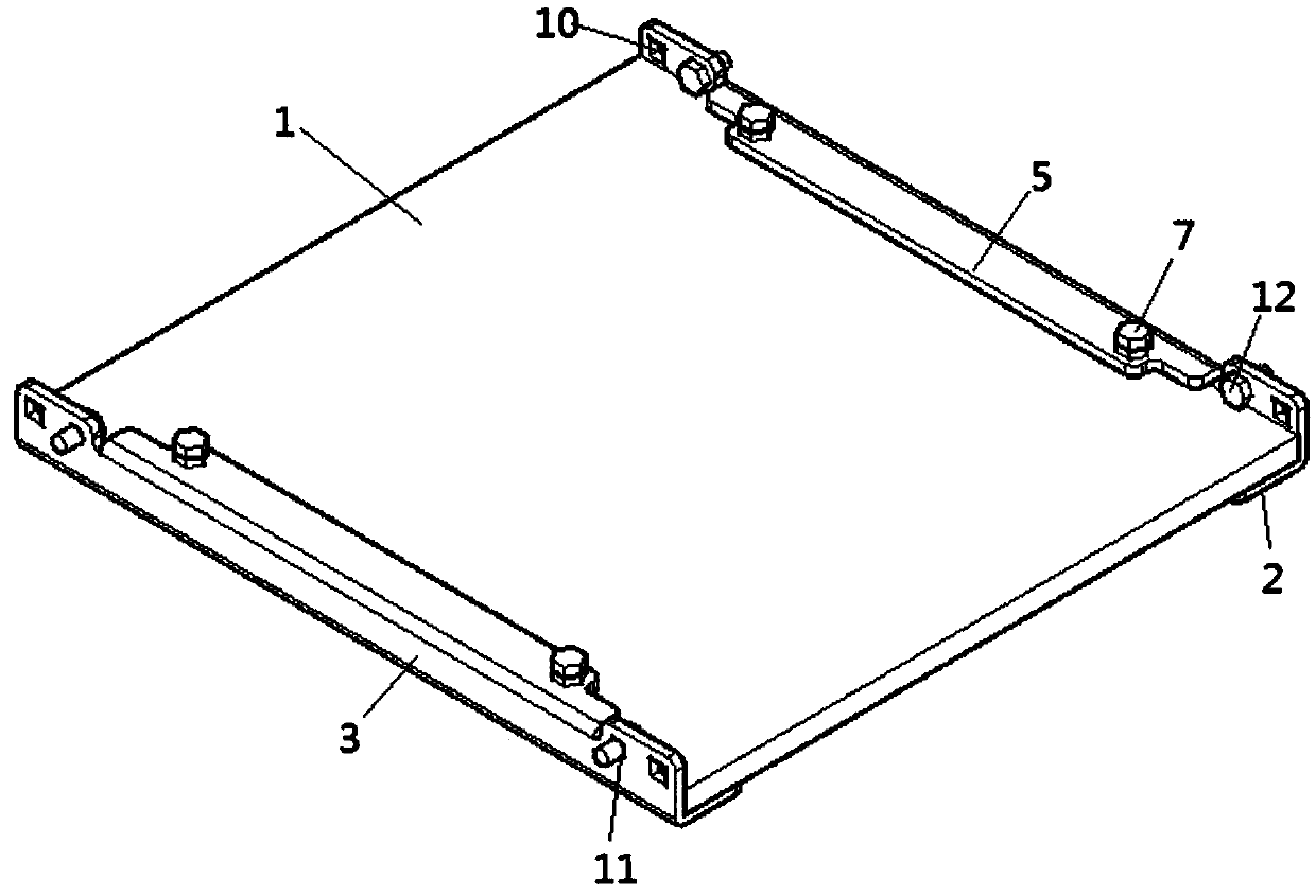
[0034] Such as image 3 The third embodiment shown is a slide rail for a cabinet mounting plate. The slide rail includes a first track plate 2 and a second track plate 3 that are perpendicular to each other. The second track plate 3 is installed and connected to the column of the cabinet through the installation structure. A concave rectangular groove is provided in the middle of the top of the track plate 3, and the bottom of the rectangular groove is connected with a clamping plate 5 that protrudes to one side and is perpendicular to the second track plate 3, and the clamping plate 5 and the first track plate 2 are located on the second track plate. On the same side of the two track plates 3, two ends of the splint 5 are respectively provided with a screw hole A, and the screw hole A is screwed with a fastening bolt A7.
[0035] The width of the first track plate 2 is equal to the width of the second track plate 3 .
[0036] Both ends of the second track plate 3 are respect...
PUM
 Abstract
Description
Claims
Application Information
 - R&D Engineer
- R&D Manager
- IP Professional
- Industry Leading Data Capabilities
- Powerful AI technology
- Patent DNA Extraction
Browse by: Latest US Patents, China's latest patents, Technical Efficacy Thesaurus, Application Domain, Technology Topic, Popular Technical Reports.
© 2024 PatSnap. All rights reserved.Legal|Privacy policy|Modern Slavery Act Transparency Statement|Sitemap|About US| Contact US: help@patsnap.com


