Supercharge Your Innovation With Domain-Expert AI Agents!

Electric locks with actuating devices for motor vehicle locks

An actuating device, a technology for motor vehicles, applied in the directions of electric locks, electric vehicle locks, power transmission/actuator features, etc., can solve the problem that the release mechanism cannot provide a locking device, etc.

Active Publication Date: 2020-10-09
KIEKERT AG
View PDF10 Cites 0 Cited by
  • Summary
  • Abstract
  • Description
  • Claims
  • Application Information

AI Technical Summary

Problems solved by technology

[0006] In extreme cases or in adverse weather conditions, which may result, much greater forces are applied to the locking device, so that the usual release mechanism cannot provide sufficient force to open the locking device

Method used


Image

  • Electric locks with actuating devices for motor vehicle locks
  • Electric locks with actuating devices for motor vehicle locks

Examples


Embodiment Construction

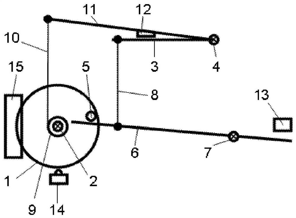
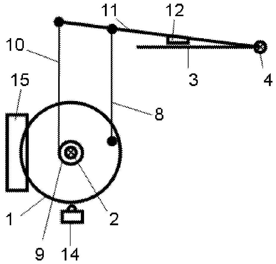
[0021] figure 1 An actuating device is shown schematically by means of which, for example, a locking pawl can be opened. An actuator 1 is shown, which can essentially be a wheel or a disc mounted rotatably via a shaft 2 . The pawl 3 can be moved out of its locking position by a rotation of the actuator 1 , in particular by a rotation in the counterclockwise direction about its axis 4 . The force for moving pawl 3 out of its locking position depends on the direction of rotation of actuator 1 . If the actuator 1 is turned in a clockwise direction about its axis 2, the actuator pin 5 mounted on the wheel on the edge side catches the rod end of the release lever 6 and thus causes the release lever 6 to rotate in an anticlockwise direction about its axis 7 swing. The actuator pin is also used as driver. This pivoting movement of the release lever 6 is transmitted to the locking pawl 3 , for example due to a lever 8 which is fastened on the one hand to the release lever 6 and on...


PUM


Abstract

The object of the invention is to always be able to open the locking device of an electrically actuated lock of a motor vehicle with sufficient force without having to provide an oversized electric motor and / or an oversized transmission ratio for this purpose. To achieve said object, a lock for a motor vehicle comprises a locking device (3) and an actuating device for opening the locking device (3). The actuating device comprises a rotatable actuator (1), which is rotatable by a motorized drive (15), in particular by an electric drive. Rotation of the actuator (1) unlocks, ie opens the locking device (3). The locking device (3) can be opened independently of the direction of rotation of the actuator (1). Therefore, the opening of the locking device (3) is not dependent on a specific direction of rotation. The force for opening the locking device (3) depends on the direction of rotation of the actuator (1). Thus, depending on the direction of rotation, opening can be achieved with different magnitudes of force. This makes it possible to open in normal operation with a lower force than would be required for opening. In normal operation—where the usual forces are sufficient for opening the locking device ( 3 )—it can thus be opened quickly and with little energy expenditure. However, it is possible to open, albeit with a delay, with greater force if necessary.

Description

technical field [0001] The invention relates to a lock with an actuating device for a door or hatch of a motor vehicle. Background technique [0002] Such a lock has a locking device / locking mechanism which in principle comprises a rotary locking fork and a locking pawl for locking the rotary locking fork in the locking position and, alternatively, a locking pawl for locking the locking pawl in its locking position. in the deadlock lever. Such a lock is known from document DE 102009026921 A1. [0003] The actuating device serves to open the door or hatch and thus enables unlocking of the locking device. The actuation of the actuating device causes the locking pawl and, if necessary, the locking lever to leave its locking position, finally opening the locking device. The door or hatch can then be opened. [0004] The actuating device usually has a release lever, which is actuated in order to open or unlock the locking device. Such a release lever is generally connected t...

Claims


Application Information

Patent Timeline
Patent Type & Authority Patents(China)
IPC IPC(8): E05B81/14E05B77/10E05B81/06E05B79/20E05B81/34
CPCE05B79/20E05B81/06E05B81/14E05B81/34E05B77/10
Inventor H·施弗尔
Owner KIEKERT AG
Features
  • R&D
  • Intellectual Property
  • Life Sciences
  • Materials
  • Tech Scout
  • Unparalleled Data Quality
  • Higher Quality Content
  • 60% Fewer Hallucinations
Learn More