Split coal dust removing device

A dust-removing device and a split-type technology are applied in the field of split-type coal dust-removing devices, which can solve the problems that the wires of the device cannot be well-limited, the coal-separated dust-removing device cannot be separated, and the influence of coal cannot be reduced, etc., and the improvement effect can be achieved. , Improve practicability and functionality, and ensure the effect of service life

Active Publication Date: 2018-04-20
JIANGSU JINENGDA ENVIRONMENTAL ENERGY SCI & TECH
View PDF3 Cites 0 Cited by
  • Summary
  • Abstract
  • Description
  • Claims
  • Application Information

AI Technical Summary

Problems solved by technology

[0004] The purpose of the present invention is to provide a split type coal dust removal device to solve the problem that the existing coal dust removal device proposed in the above background technology cannot separate and separate the coal dust well, so that it cannot reduce the mutual interaction between coal. impact, and the dust removal of coal is not thorough enough, the dust attached to the coal is difficult to fall, the dust after dust removal is not easy to clean, and the wires on the device cannot be well limited, which is prone to danger, clamping The jig used for coal cannot be placed conveniently, and the jig is easily corroded when it is in direct contact with the air

Method used


Image

  • Split coal dust removing device
  • Split coal dust removing device
  • Split coal dust removing device

Examples


Embodiment Construction

[0021] The following will clearly and completely describe the technical solutions in the embodiments of the present invention with reference to the accompanying drawings in the embodiments of the present invention. Obviously, the described embodiments are only some, not all, embodiments of the present invention. Based on the embodiments of the present invention, all other embodiments obtained by persons of ordinary skill in the art without making creative efforts belong to the protection scope of the present invention.

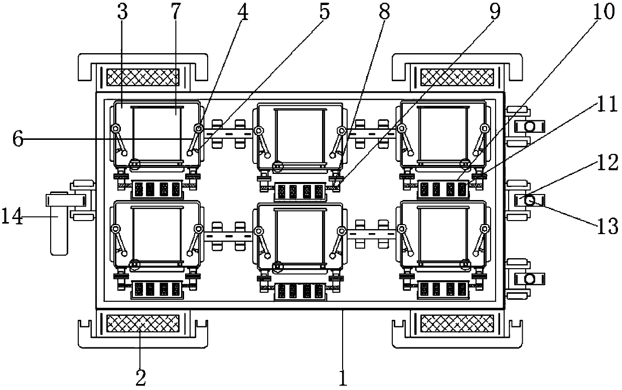
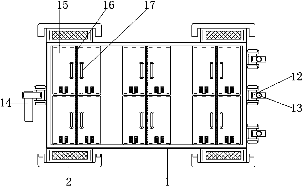
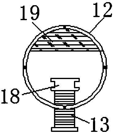
[0022] see Figure 1-5 , the present invention provides a technical solution: a split type coal dust removal device, including a dust removal device main body 1, a foot 2, a split tank 3, a rotating shaft 4, a hydraulic cylinder 5, a knocking rod 6, and a split dust removal box 7 , groove 8, connection block 9, dust box 10, observation port 11, limit block 12, limit bolt 13, placement groove 14, door body 15, magnetic strip 16, handle 17, limit block 18, fixed...


PUM


Abstract

The invention relates to a split coal dust removing device. The split coal dust removing device comprises a dust removing device body, grooves, dust collecting boxes, limiting blocks and limiting cushion blocks. Bottom feet are arranged on the left side and the right side of the bottom end of the dust removing device body. Split grooves are embedded in the dust removing device body. The inner walls of the split grooves are connected with rotation shafts. Knocking rods are arranged at the bottom ends of the rotation shafts. The bottom ends of the knocking rods are connected with hydraulic air cylinders. Split dust removing boxes are arranged on the inner sides of the knocking rods. The grooves are formed in the left sides and the right sides of the lower portions of the split dust removingboxes. Connecting blocks are arranged in the grooves. The dust collecting boxes are located below the split dust removing boxes. Observation ports are embedded in the outer surfaces of the dust collecting boxes. The limiting blocks are arranged at the right ends of the dust removing device body, and limiting bolts penetrate the limiting blocks. The split coal dust removing device has the beneficial effects that according to the split coal dust removing device, the six split dust removing boxes are arranged so that coal can be well isolated, and coal is subjected to separation and dust removal.

Description

technical field [0001] The invention relates to the technical field of coal production devices, in particular to a split coal dust removal device. Background technique [0002] In the process of coal mining, a large amount of dust will be mixed into the raw coal, which will not only affect the quality of the coal, but also have an adverse effect on the subsequent washing process, which will have a huge impact on the later stage, and even cause major accidents in severe cases Therefore, before the selection and washing process, the dust in the raw coal needs to be removed in advance, so it is necessary to use a coal dust removal device to remove dust from the coal. [0003] Existing coal dedusting devices cannot separate and dedust coal well, so that the mutual influence of coal cannot be reduced, and the dedusting of coal is not thorough enough, and the dust adhering to coal is difficult to fall off. The dust left behind is not easy to clean, and the wires on the device can...

Claims


Application Information

Patent Timeline
Patent Type & Authority Applications(China)
IPC IPC(8): B08B7/02B08B15/04B08B13/00
CPCB08B7/02B08B13/00B08B15/04
Inventor 贾兴仕刘从振张泽旭凌爱民杨苗苗
Owner JIANGSU JINENGDA ENVIRONMENTAL ENERGY SCI & TECH
Why Eureka
Try Eureka