
Machining method of nozzle sleeve mounting side

A processing method and nozzle technology, applied in metal processing equipment, manufacturing tools, turning equipment, etc., can solve problems such as easy deformation of the installation edge, and achieve the effects of improving the pass rate, reducing deformation, and increasing rigidity

Active Publication Date: 2018-04-20
CHINA HANGFA SOUTH IND CO LTD
View PDF7 Cites 2 Cited by
  • Summary
  • Abstract
  • Description
  • Claims
  • Application Information

AI Technical Summary

Problems solved by technology

[0004] The invention provides a method for processing the mounting edge of a spout sleeve to solve the technical problem that the mounting edge is easily deformed during processing

Method used


Image

  • Machining method of nozzle sleeve mounting side
  • Machining method of nozzle sleeve mounting side
  • Machining method of nozzle sleeve mounting side

Examples


Embodiment Construction

[0031] It should be noted that, in the case of no conflict, the embodiments in the present application and the features in the embodiments can be combined with each other. The present invention will be described in detail below with reference to the accompanying drawings and examples.

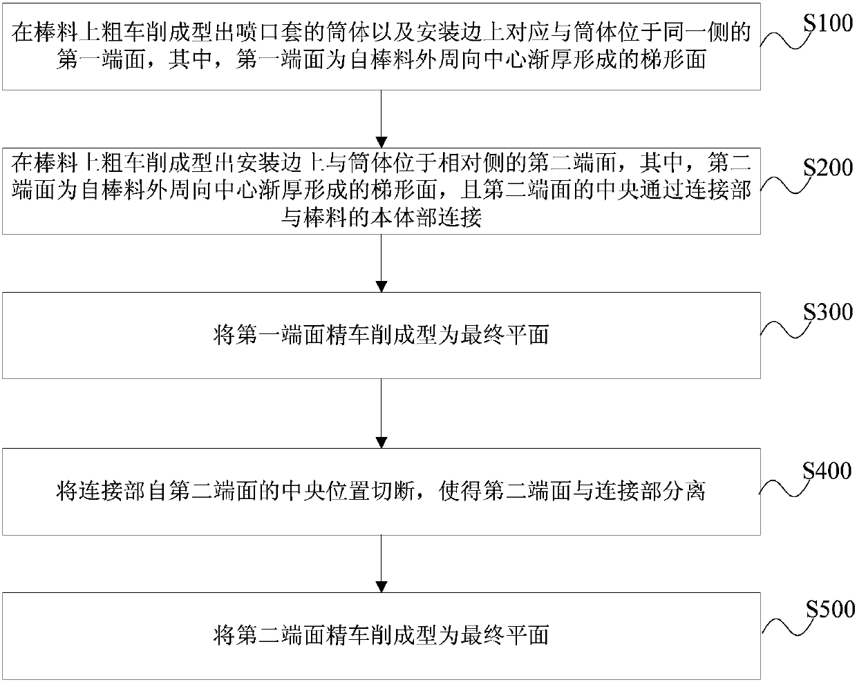
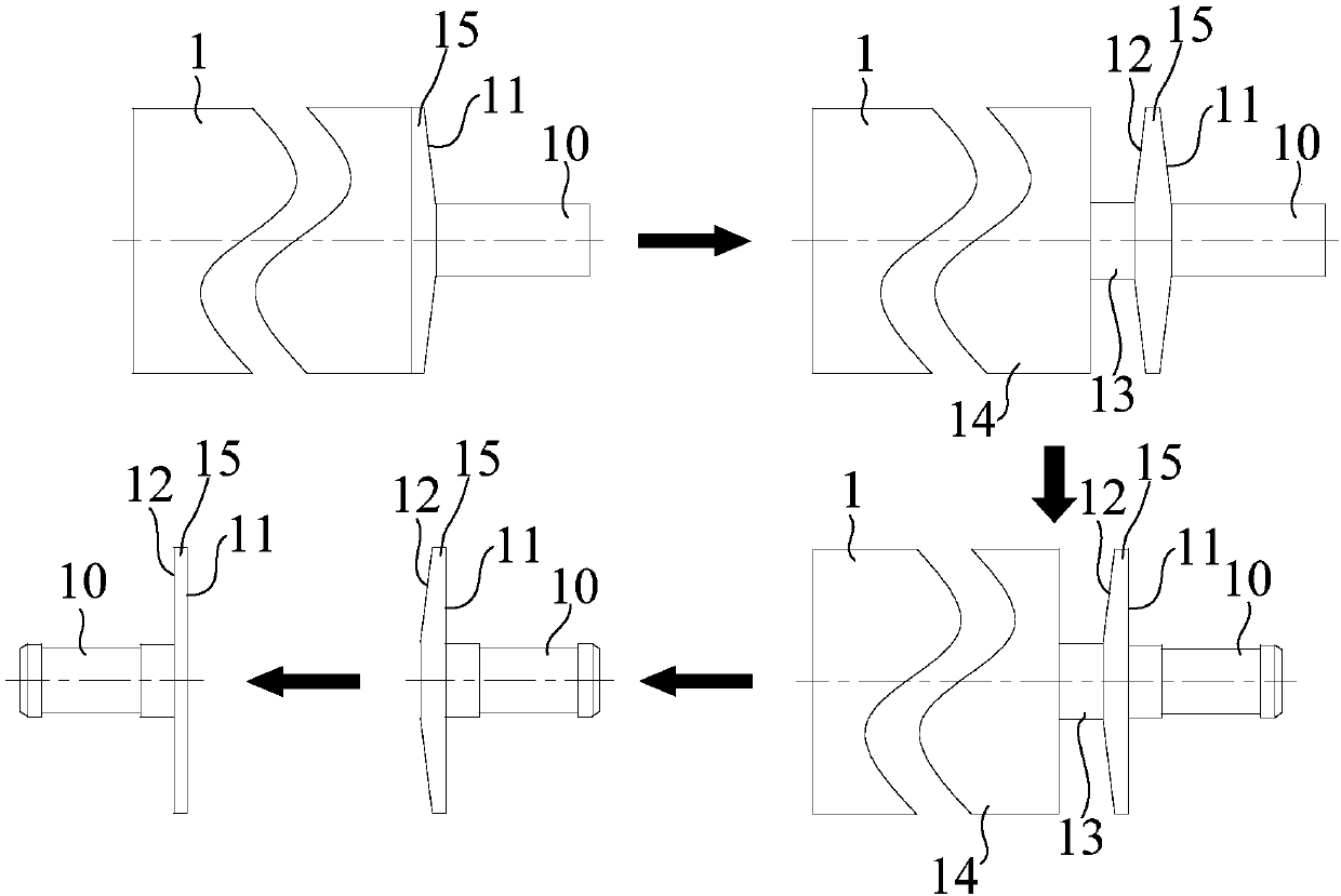
[0032] refer to figure 2 and image 3 , a preferred embodiment of the present invention provides a method for processing the mounting edge of the spout sleeve, comprising the following steps:

[0033] Step S100, the first end surface 11 corresponding to the same side as the cylinder body 10 on the cylinder body 10 and the installation edge 15 of the bar stock 1 formed by rough turning, wherein the first end surface 11 is from the outer circumference direction of the bar stock 1 Trapezoidal face formed by gradually thickening center.

[0034] Step S200, rough turning on the bar 1 to form a second end surface 12 on the side opposite to the barrel 10 on the mounting edge 15, wherein the second...


PUM


Abstract

The invention discloses a machining method of a nozzle sleeve mounting side. The method comprises the steps that a cylinder of a nozzle sleeve and a first end face, correspondingly located on the sameside with the cylinder, on the mounting side are roughly turned and formed on a bar, wherein the first end face is a ladder-shaped face gradually thickening from the periphery of the bar to the center; a second end face, on the opposite side of the cylinder, on the mounting side is roughly turned and formed on the bar, the second end face is a ladder-shaped face gradually thickening from the periphery of the bar to the center, and the center of the second end face is connected with a body part of the bar through a connecting part; the connecting part is cut off from the central position of the second end face, and therefore the second end face and the connecting part are separated. The first end face and the second end face on the two sides of the nozzle sleeve mounting side are roughly turned and machined into the ladder-shaped faces, the thickness of the mounting side is gradually increased from the periphery to the center, rigidity of the mounting side is increased, in the cutting-off process, the precision of the mounting side is not affected, deformation of the mounting side in the machining process is reduced, and the yield of the nozzle sleeve is improved.

Description

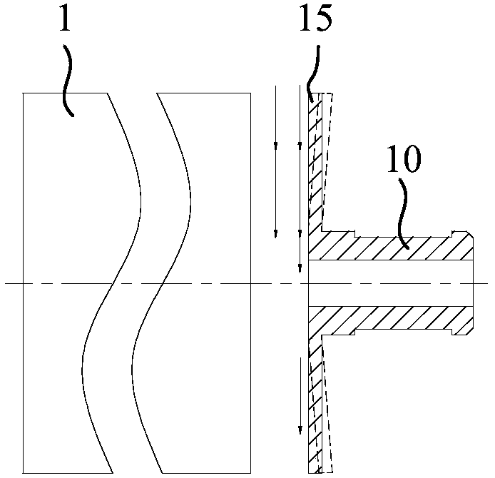
technical field [0001] The invention relates to the technical field of processing the mounting edge of an aero-engine nozzle sleeve, in particular, to a processing method for the mounting edge of a nozzle sleeve. Background technique [0002] The nozzle sleeve of the aero-engine is made of the bar stock 1. After turning to remove the allowance, the thickness of the mounting edge 15 is only 1mm, and the width is as large as 17.8mm, and the parallelism of the two sides is required to be no more than 0.05mm. [0003] At present, the processing method of the mounting edge of the spout sleeve is relatively backward. The existing processing method is usually to finish turning the two opposite end faces of the mounting edge on the bar, and then cut the spout sleeve from the bar horizontally. The cutting direction is as follows: figure 1 indicated by the middle arrow. In the process of cutting the spout sleeve, it is subjected to transverse cutting force, and the rigidity of the mo...

Claims


Application Information

Patent Timeline
Patent Type & Authority Applications(China)
IPC IPC(8): B23B5/00B23B1/00
CPCB23B1/00B23B5/00
Inventor 徐舟宁雄万坤胡志星叶才铭杨建辉郑学著刘青海
Owner CHINA HANGFA SOUTH IND CO LTD
Learn More