Free movement device of seat

A motion device, free technology, applied in the direction of movable seats, transportation and packaging, body, etc., can solve the problems of unsatisfactory seat safety and comfort, and achieve the effect of solving comfort, easy mass production, and low failure.

Pending Publication Date: 2018-04-20
黄继成
0 Cites 1 Cited by

AI-Extracted Technical Summary

Problems solved by technology

[0002] At present, due to the deficiencies in the design, the seats of the existing agricultural machine...

Abstract

A seat free movement device, comprising a load-bearing rotating shaft, a rotating shaft body fixing frame, a longitudinal sliding frame, a seat back fixing block, an up and down sliding frame and connecting pins; the load-bearing rotating shaft is connected with the rotating shaft body fixing frame , the load-bearing rotating shaft is connected with the longitudinal sliding frame, the longitudinal sliding frame is installed on the up and down sliding frame, and the up and down sliding frame is connected with the seat back fixing block through a connecting pin. Utilizing the present invention can solve the problem of the comfort of agricultural machinery when working on a slope, and can adjust the center of gravity to a certain extent to improve the safety of working on a slope. It can also be used to improve the comfort of other machinery such as off-road vehicles. and center of gravity control.

Application Domain

Technology Topic

Image

  • Free movement device of seat
  • Free movement device of seat
  • Free movement device of seat

Examples

  • Experimental program(1)

Example Embodiment

[0019] The present invention will be further described below with reference to the drawings and embodiments.
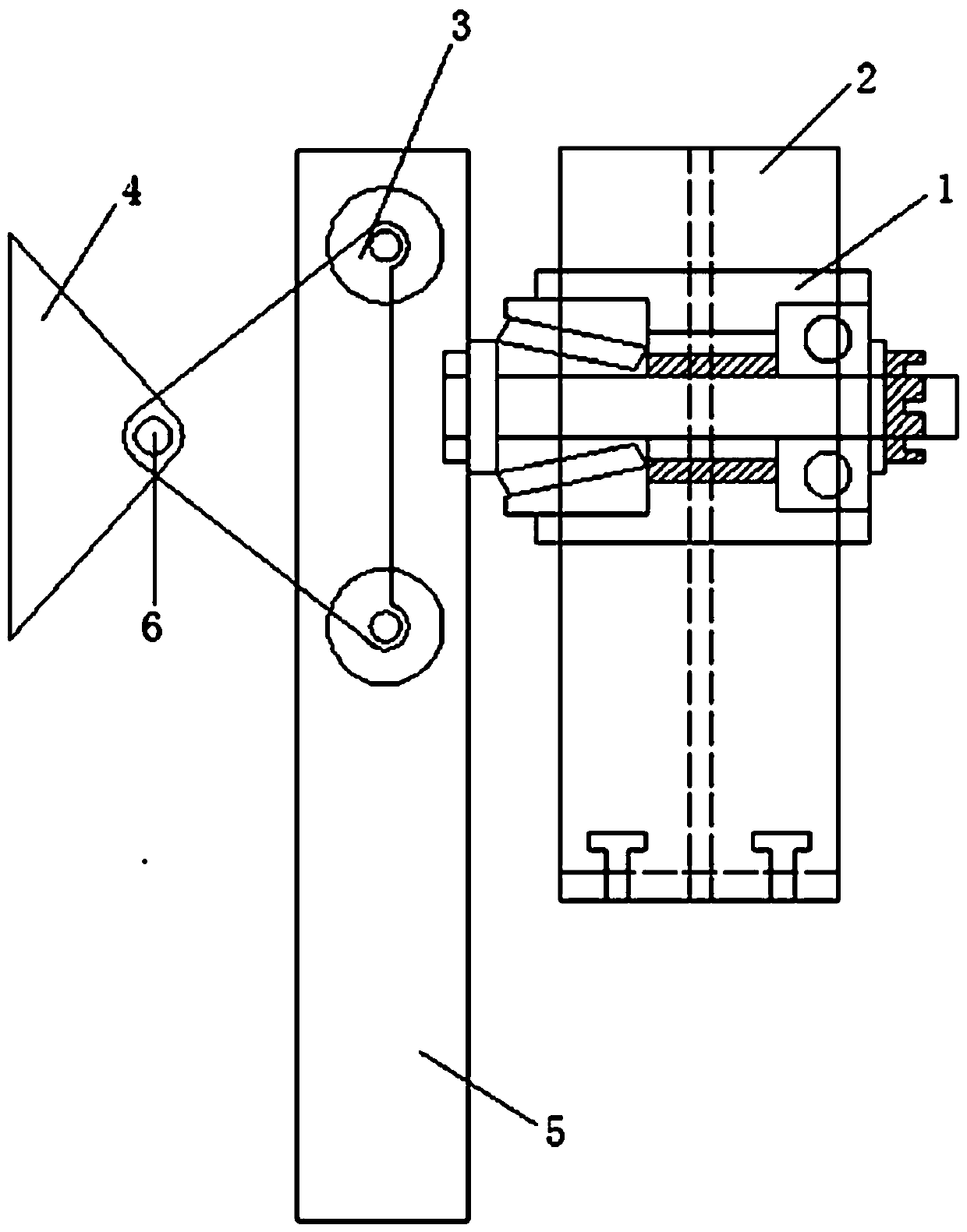
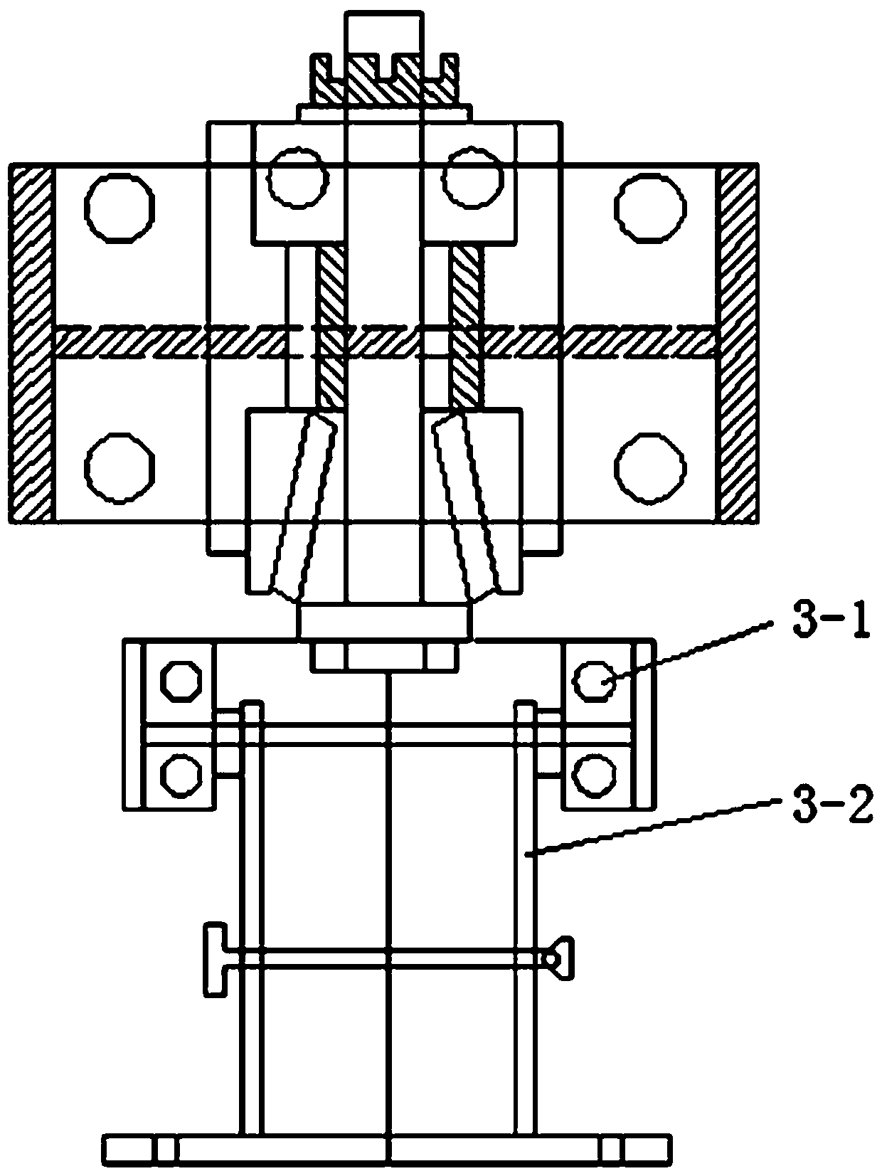
[0020] With reference to the drawings, this embodiment includes a load-bearing rotating shaft 1, a rotating shaft body fixing frame 2, a longitudinal sliding frame 3, a seat back fixing block 4, a vertical sliding frame 5 and a connecting pin 6; The shaft fixing frame 2 is connected, the load-bearing rotating shaft 1 is connected with the longitudinal sliding frame 3, the longitudinal sliding frame 3 is installed on the vertical sliding frame 5, and the vertical sliding frame 5 is connected to the seat through a connecting pin 6 The seat back fixing block 4 is connected.
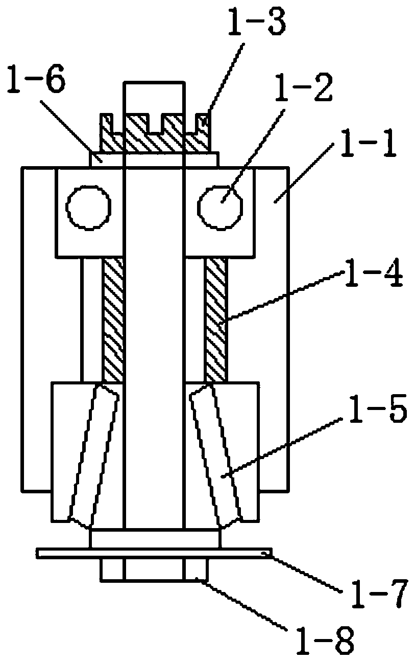
[0021] In this embodiment, the load-bearing rotating shaft 1 includes a load-bearing rotating shaft body 1-1, a deep groove ball bearing 1-2, a slotted nut 1-3, a top column 1-4 between the bearings, a tapered bearing 1-5, Spring washer 1-6, flat washer 1-7, rotating screw 1-8; the deep groove ball bearing 1-2 and the tapered bearing 1-5 are assembled in two bearing positions of the load-bearing rotating shaft body 1-1, The middle is supported by the top post 1-4 between the bearings, and the rotating screw 1-8 passes through the middle of the load-bearing rotating shaft body 1-1 via the flat washer 1-7 to connect with the spring washer 1-6 and the slotted nut 1-3 .
[0022] In this embodiment, the longitudinal sliding frame 3 includes a longitudinal sliding bearing 3-1 and a longitudinal sliding bearing fixing frame 3-2, and the longitudinal sliding bearing 3-1 is installed in the longitudinal sliding bearing fixing frame 3-2.
[0023] In this embodiment, the up and down sliding frame 5 is provided with an up and down sliding groove 5-1 and a rotating fixing screw hole 5-2.
[0024] Use: Load-bearing rotating shaft body 1-1 is welded to the center hole of the rotating shaft body fixing frame 2, the four nuts of the base of the rotating shaft body fixing frame 2 are locked and fixed with the external fixed point, deep groove ball bearing 1-2 and cone type Bearings 1-5 are mounted on the two bearing positions of the load-bearing rotating shaft body 1-1, the middle is supported by the top post 1-4 between the bearings, and the rotating screw 1-8 plus the flat pad 1-7 are used to rotate the fixed screw hole 5-2 is fixed with tapered bearing 1-5, so that the vertical sliding frame 5 can be rotated 360 degrees. The four longitudinal sliding bearings 3-1 are fixed by the longitudinal sliding bearing fixing frame 3-2, which can slide up and down in the upper and lower sliding grooves 5-1. The longitudinal sliding bearing fixing frame 3-2 is connected with the seat back longitudinal fixing frame. They are connected by a connecting pin 6, so that the seat back fixing block 4 can make a certain tilting movement, and the seat back fixing block is locked with the seat back. The seat can move up and down, forward and backward, and rotate.
[0025] The present invention utilizes a free-moving mechanical method, which can bear pressure in one direction and can also move in multiple directions freely. After the seat is installed, the angle of the side fixed with the machine can be changed. When it does not affect the level of the seat, the seat can use the downward gravity to keep the seat always in a vertical downward direction.

PUM

no PUM

Description & Claims & Application Information

We can also present the details of the Description, Claims and Application information to help users get a comprehensive understanding of the technical details of the patent, such as background art, summary of invention, brief description of drawings, description of embodiments, and other original content. On the other hand, users can also determine the specific scope of protection of the technology through the list of claims; as well as understand the changes in the life cycle of the technology with the presentation of the patent timeline. Login to view more.

Similar technology patents

Backlight module, back plate and liquid crystal display device

InactiveCN102537777AImprove versatilityReduce production and processing costsNon-linear opticsLight fasteningsLiquid-crystal displayBackplane
Owner:TCL CHINA STAR OPTOELECTRONICS TECH CO LTD

Method of producing high quality semicoke using low grade brown coal

InactiveCN100545237CSimple processReduce production and processing costsCoke ovensSpecific gravityBrown coal
Owner:云南冶金集团总公司技术中心

Environment-friendly 310 stainless steel powder feed and preparing method of 310 stainless steel powder part

InactiveCN109047750AChange the disadvantages of difficult processing, long processing cycle and high processing costReduce production and processing costsTransportation and packagingMetal-working apparatusMetal powderAlloy
Owner:DONGGUAN HUAJING POWDER METALLURGY

Classification and recommendation of technical efficacy words

  • Reduce production and processing costs
  • Easy mass production

Apple juice processing method

InactiveCN103222657AReduce production and processing costsExtended shelf lifeFood scienceChemistryProcess engineering
Owner:李晓昭

Preparation method of anti-cutting polyethylene fibers

InactiveCN108277546ASimple processReduce production and processing costsMonocomponent polyolefin artificial filamentArtifical filament manufactureFiberUltrahigh molecular weight polyethylene
Owner:HUNAN ZHONGTAI SPECIAL EQUIP

Automobile part laser marking device

InactiveCN104084695AImprove marking accuracy and speedReduce production and processing costsPrintingLaser beam welding apparatusDrive motorEngineering
Owner:JIANGSU SECURE AUTO PARTS

Multi-gear static zoom lens based on super-surface material

InactiveCN110412761ASimple optical structure and mechanical structureEasy mass productionLensPolarizerOptoelectronics
Owner:WUHAN UNIV

Light guide plate, method for manufacturing the same and backlight unit using the same

ActiveUS20100157626A1Easy mass productionLow weight and thinnessPrismsMechanical apparatusPrismUV curing
Owner:LG DISPLAY CO LTD

Method for producing gaba mochi barley containing gaba and product thereof

ActiveUS20120324607A1Easy mass productionAngiosperms/flowering plantsFood scienceChemistryGlutamate decarboxylase
Owner:MAEDA CORPORATION +1
Why Eureka
Try Eureka