Multifunctional obstacle crossing robot

A robot and multi-functional technology, applied in the direction of motor vehicles, transportation and packaging, etc., can solve the problems of exposed transmission structure, poor reliability, and easy failure of obstacle-crossing robots, so as to achieve simple and ingenious mechanical structure design, small possibility, The effect of simple transmission structure

Active Publication Date: 2018-04-20
苏州智德金网络科技股份有限公司
View PDF8 Cites 2 Cited by
  • Summary
  • Abstract
  • Description
  • Claims
  • Application Information

AI Technical Summary

Problems solved by technology

[0002] Obstacle-crossing robots can be used in various fields such as military survey and exploration, and have been well developed. At present, there are many kinds of obstacle-crossing robots, but most traditional obstacle-crossing robots have a big defect. Most traditional obstacle-crossing robots The number of motors that provide power in the robot is large, and often each obstacle-crossing wheel needs a separate motor to drive, and the structure of the traditional obstacle-crossing robot is very complicated, many transmission structures are exposed, and the complex structure itself cooperates with a large number of Power motors make traditional obstacle-crossing robots prone to failure and poor reliability, and the steering of traditional obstacle-crossing robots is mostly not flexible enough. In harsh environments, it is difficult for traditional longer robots to guarantee reliability

Method used


Image

  • Multifunctional obstacle crossing robot
  • Multifunctional obstacle crossing robot
  • Multifunctional obstacle crossing robot

Examples


Embodiment Construction

[0011] In order to make the purpose, technical solutions and advantages of the embodiments of the present invention clearer, the technical solutions in the embodiments of the present invention will be clearly and completely described below in conjunction with the drawings in the embodiments of the present invention. Obviously, the described embodiments It is a part of embodiments of the present invention, but not all embodiments. Based on the embodiments of the present invention, all other embodiments obtained by persons of ordinary skill in the art without creative efforts fall within the protection scope of the present invention.

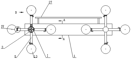
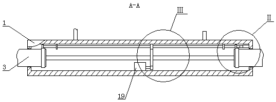
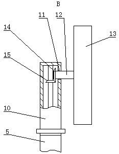
[0012]A multifunctional obstacle-surmounting robot, as shown in the figure, includes a box body 1, two first through holes 2 are opened on the front and rear ends of the box body 1, the two first through holes 2 on the front end face and the two first through holes 2 on the rear end face The two first through holes 2 are correspondingly opened sym...


PUM


Abstract

A multifunctional obstacle crossing robot comprises a box. Two first through holes are formed in each of the front end face and the rear end face of the box. The two first through holes in the front end face and the two first through holes in the rear end face are correspondingly and symmetrically formed. The two first through holes in the same end face are close to the left end and the right endof the box. Transverse pipes are arranged in the first through holes and movably connected with bearings of the corresponding first through holes. The inner ends of the transverse pipes are located inthe box. Each advancing power shaft is arranged in the two coaxial transverse pipes located on the front side and the rear side of the box. The two ends of each advancing power shaft are located in the outer ends of the corresponding transverse pipes. The advancing power shafts and the transverse pipes are connected through bearings. Every four connecting pipes are fixedly installed on the periphery of the outer end of one transverse pipe and evenly distributed according to the center axis of the corresponding transverse pipe. The multifunctional obstacle crossing robot can easily cross mostobstacles and is suitable for various fields of military reconnaissance, disaster area material transport, expedition and the like, various devices can be installed on the robot in a matched mode to conduct different jobs, and functions are diverse.

Description

technical field [0001] The invention belongs to the technical field of obstacle-surmounting robots, in particular to a multifunctional obstacle-surmounting robot. Background technique [0002] Obstacle-crossing robots can be used in various fields such as military survey and exploration, and have been well developed. At present, there are many kinds of obstacle-crossing robots, but most traditional obstacle-crossing robots have a big defect. Most traditional obstacle-crossing robots The number of motors that provide power in the robot is large, and often each obstacle-crossing wheel needs a separate motor to drive, and the structure of the traditional obstacle-crossing robot is very complicated, many transmission structures are exposed, and the complex structure itself cooperates with a large number of Power motors make traditional obstacle-crossing robots prone to failure and poor reliability, and the steering of traditional obstacle-crossing robots is mostly not flexible e...

Claims


Application Information

Patent Timeline
Patent Type & Authority Applications(China)
IPC IPC(8): B62D57/02
CPCB62D57/02
Inventor 赵越
Owner 苏州智德金网络科技股份有限公司
Why Eureka
Try Eureka