
Double-layer comprehensive pipe rack provided with ventilation port and escape port node structures

A node structure and comprehensive pipe gallery technology, which is applied to underwater structures, infrastructure projects, water conservancy projects, etc., can solve the problems of many outlets protruding from the ground, reduce the number of nodes, and occupy a large space, so as to reduce the difficulty of construction, The effect of reducing the number of nodes and reducing the occupied space

Active Publication Date: 2018-04-20
MCC CAPITAL ENGINEERING & RESEARCH
View PDF9 Cites 4 Cited by
  • Summary
  • Abstract
  • Description
  • Claims
  • Application Information

AI Technical Summary

Problems solved by technology

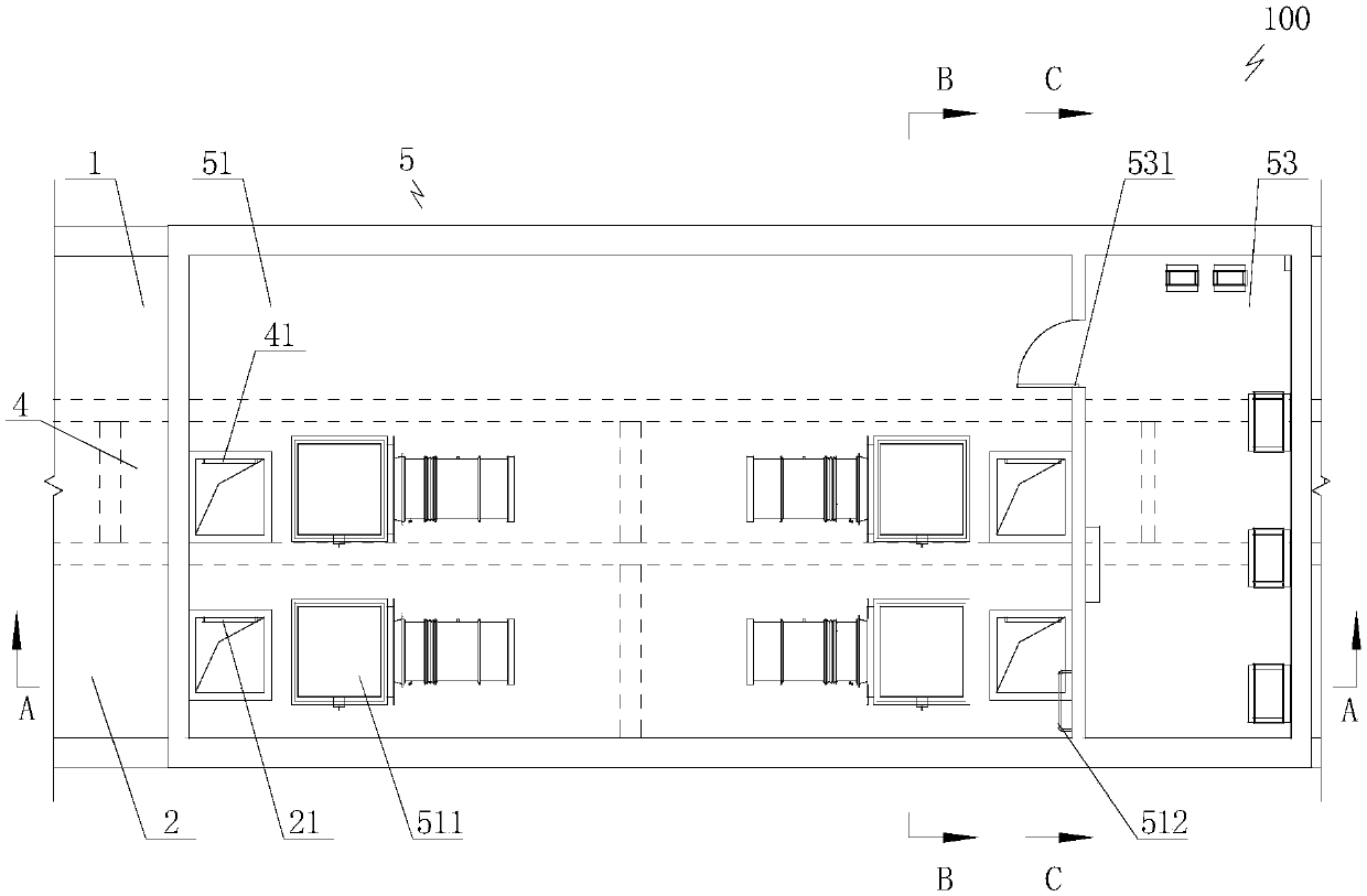
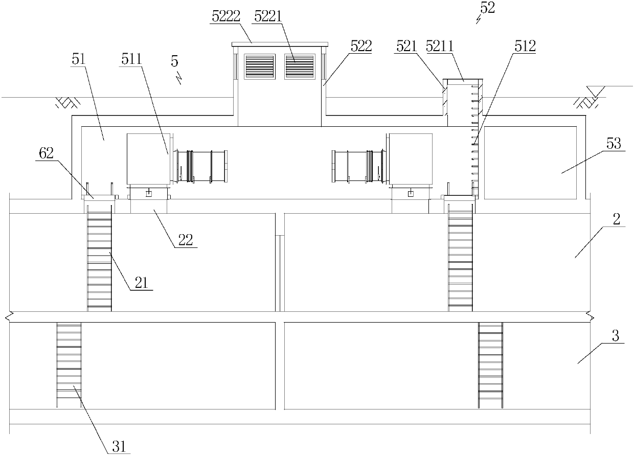
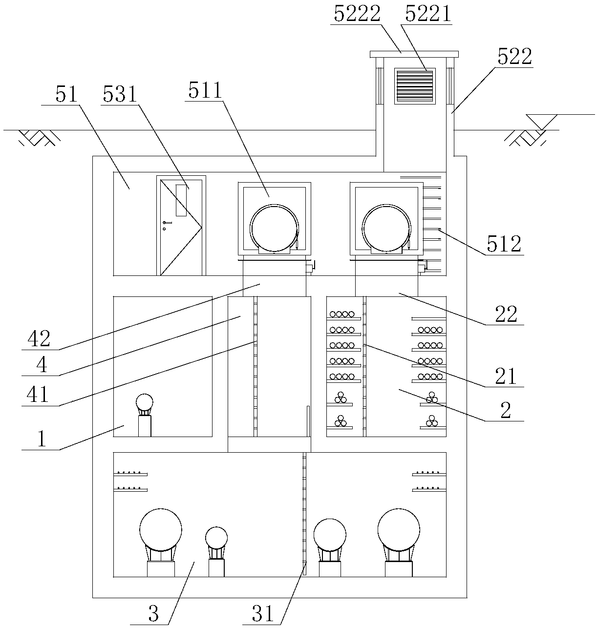
[0007]The purpose of the present invention is to provide a double-layer integrated pipe gallery with a node structure of ventilation openings and escape ports, which overcomes the single-layer integrated pipe gallery existing in the prior art. The cross-sectional direction of the corridor occupies a large space, there are many exits protruding from the ground, the construction is difficult, and the cost is high. The double-layer comprehensive pipe gallery can effectively reduce the space occupied by the cross-section. The joint structure of the vent and the escape port satisfies the functions of the vent and the escape port at the same time, which can effectively reduce the number of nodes, reduce the construction difficulty and construction cost

Method used


Image

  • Double-layer comprehensive pipe rack provided with ventilation port and escape port node structures
  • Double-layer comprehensive pipe rack provided with ventilation port and escape port node structures
  • Double-layer comprehensive pipe rack provided with ventilation port and escape port node structures

Examples


Embodiment Construction

[0039] In order to have a clearer understanding of the technical features, purposes and effects of the present invention, the specific implementation manners of the present invention will now be described with reference to the accompanying drawings.

[0040] Such as Figure 1 to Figure 4As shown, the present invention provides a double-layer comprehensive pipe gallery 100 provided with a node structure of vents and escape ports, and natural gas tanks arranged at intervals are arranged in the double-layer comprehensive pipe gallery 100 provided with a node structure of vents and escape ports 1. The electric cabin 2 and the integrated cabin 3, the natural gas cabin 1 can accommodate natural gas pipelines, the electric cabin 2 can accommodate power pipelines and communication pipelines, and the integrated cabin 3 can accommodate water supply pipelines, regenerated water pipelines, heat pipelines and communication The pipeline, the natural gas cabin 1 and the electric cabin 2 are ...


PUM


Abstract

The invention discloses a double-layer comprehensive pipe rack provided with ventilation port and escape port node structures. The double-layer comprehensive pipe rack is internally provided with a natural gas cabin, an electric cabin and a comprehensive cabin; the natural gas cabin and the electric cabin are arranged above the comprehensive bin to form a double-layer arrangement structure; a function cabin capable of communicating with the comprehensive cabin is formed between the natural gas cabin and the electric cabin; the ventilation port and escape port node structures capable of communicating with the external and capable of being sealed are longitudinally arranged at the top at intervals; the ventilation port and escape port node structures can communicate with the electric cabin and the function cabin correspondingly, and comprise fan equipment chambers; and function through port structures capable of communicating with the upper side of the ground and capable of being sealedare arranged at the tops of the fan equipment chambers. The pipe rack can effectively reduce the cross section occupied space; and the ventilation port and escape port node structures arranged at thetop meet the functions of ventilation ports and escape ports at the same time, so that the node number can be effectively reduced, and the construction difficulty and the construction cost are reduced.

Description

technical field [0001] The invention relates to the technical field of urban comprehensive pipe gallery, in particular to a double-layer comprehensive pipe gallery provided with node structures of ventilation openings and escape ports. Background technique [0002] The comprehensive pipe gallery is a structure and ancillary facilities built underground to accommodate two or more types of urban engineering pipelines. That is to build a tunnel space underground in the city, integrating various engineering pipelines such as power, communication, gas, heating, water supply and drainage, etc., with special inspection ports, hoisting ports and monitoring systems, which is an important basis for ensuring urban operation Facilities and "lifelines". The construction of comprehensive utility corridors can effectively eliminate urban "pull links", ensure smooth road traffic, and ensure safe operation of underground pipelines. [0003] "Technical Specifications for Urban Comprehensive...

Claims


Application Information

Patent Timeline
Patent Type & Authority Applications(China)
IPC IPC(8): E02D29/045
CPCE02D29/045E02D29/10
Inventor 宗金宇张晓蕾尹力文张连海阙良刚姜素云胡悦黄喆薛攀
Owner MCC CAPITAL ENGINEERING & RESEARCH
Learn More