Supporting structure of the end of laminated plate at laminated beam position and high-altitude concrete pouring method

A technology of supporting structure and laminated board, which is applied to the on-site preparation of building components, construction, building structure, etc., can solve the problems of unstable supporting beam structure, influence on the stability of laminated board, and difficult to remove the supporting structure. Ease of disassembly, improved stability, and reduced installation requirements

Pending Publication Date: 2018-04-20
中建科技成都有限公司
View PDF6 Cites 3 Cited by
  • Summary
  • Abstract
  • Description
  • Claims
  • Application Information

AI Technical Summary

Problems solved by technology

The accumulation of concrete will not only bring pressure to the support beam, make the structure of the support beam unstable, and affect the stability of the laminated slab; the concrete in the groove is bound to continue to flow down along the gap between the support frame and the shear wall, It flows into the gap between the fixing device and the shear wall, and between the fixing device and the supporting frame. After the concrete solidifies, the supporting structure is not easy to remove; Large, so that the horizontal fixing device cannot be dismantled, that is, the entire supporting structure cannot be dismantled

Method used


Image

  • Supporting structure of the end of laminated plate at laminated beam position and high-altitude concrete pouring method
  • Supporting structure of the end of laminated plate at laminated beam position and high-altitude concrete pouring method

Examples


Embodiment 1

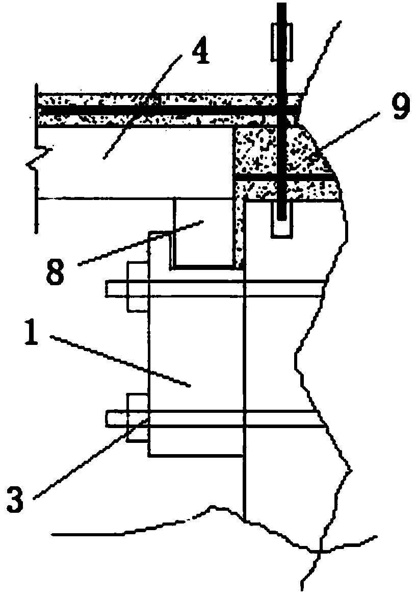
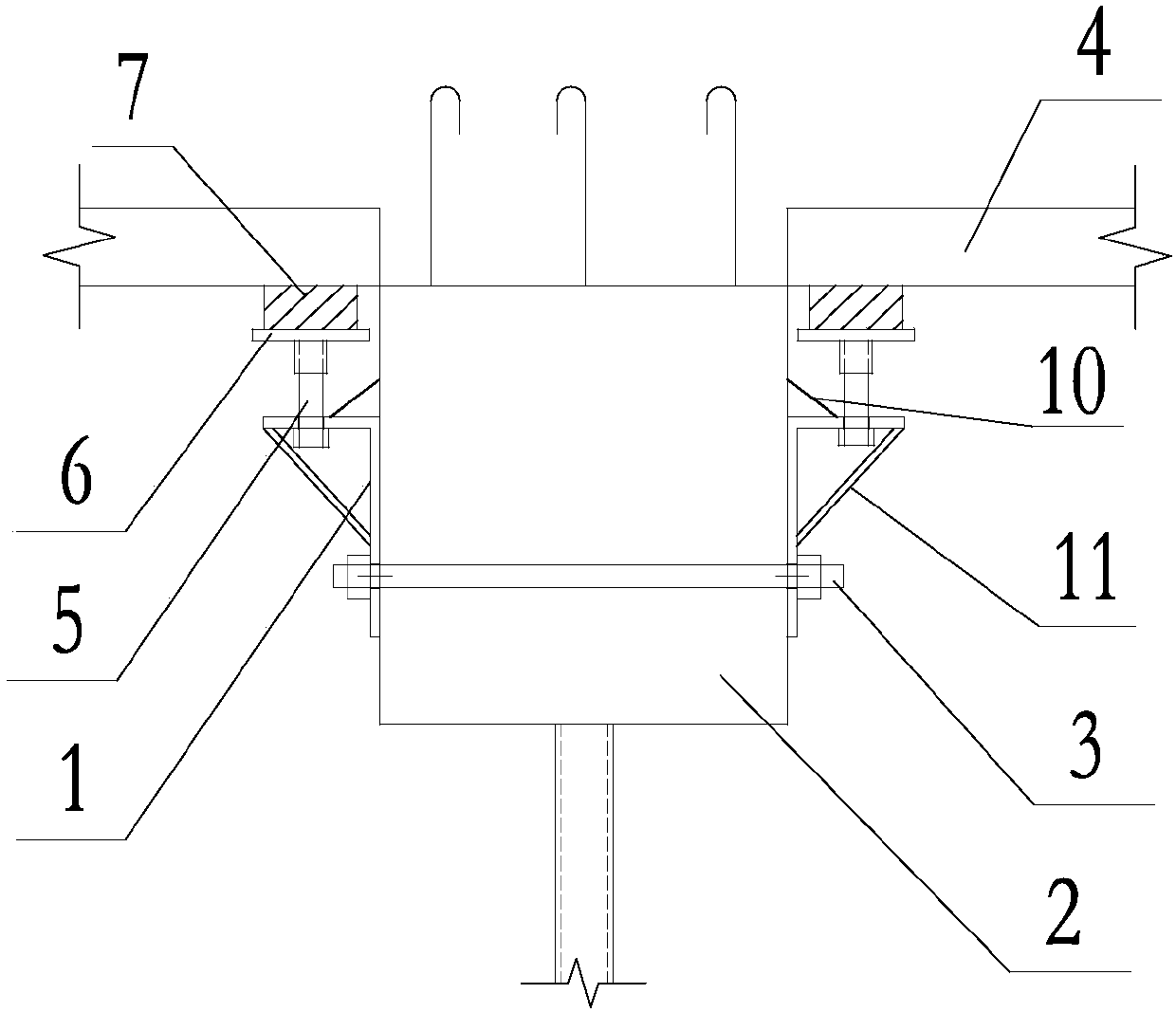
[0030] Such as figure 2 A support structure with the end of the laminated plate at the laminated beam is shown, including a support frame 1, a fixing device 3, a bolt 5, and a flat sleeve 6 sleeved on the upper end of the bolt 5, and the fixing device 3 is used to fix the support frame 1. The bolt 5 is set on the support frame 1 through the screw hole. During construction, the support frame 1 is fixed on the beam 2 through the fixing device 3, the upper end surface of the flat sleeve 6 is in contact with the end of the laminated plate 4 to support the laminated plate 4, and the force of the laminated plate passes through the flat sleeve 6 and the bolt 5 , The support frame 1 acts on the beam 2. All the orientation words mentioned in this scheme, such as, upper, lower, upper face, etc., all refer to the state orientation words during normal use.

Embodiment 2

[0032] This embodiment is optimized on the basis of embodiment 1, specifically:

[0033] A buffer layer 7 is provided on the upper end surface of the flat sleeve 6 . The buffer layer can be made of wood squares, plastic boards, or rubber pads, and it is sufficient to ensure that the upper end of the buffer layer is flat during the construction process.

[0034] A drainage structure 10 for guiding concrete to the outside of the support frame 1 is arranged on the upper end surface of the support frame 1 .

[0035] The drainage structure can adopt a variety of structures, such as: a right-angled triangular prism structure, whose right-angled side is fixed on the upper end surface of the support frame 1, and the other right-angled side is attached to the beam; or it is a shrapnel structure, and one side of the shrapnel structure is fixed on the The upper end surface of the support frame 1, and the opposite side has a tendency to press down toward the beam side.

[0036] In order...

Embodiment 3

[0038] Based on the supporting structures of Embodiment 1 and Embodiment 2, this embodiment discloses a method for pouring high-altitude concrete, including the following steps:

[0039] A, the support frame 1 of embodiment 1, 2 is fixed on the beam 2 by fixing device 3;

[0040] B, adjust the height of the bolt 5 of embodiment 1, 2, make the upper end surface of buffer layer 7 not be lower than the beam upper end surface;

[0041]C, place the laminated plate 4, place the end of the laminated plate 4 on the buffer layer 7, at this time, if the lower end surface of the laminated plate 4 is higher than the upper end surface of the beam, then adjust the bolt 5 to make the lower end surface of the laminated plate 4 and the beam The upper end face is flush, and the edge of the laminated plate is in contact with the edge of the beam;

[0042] D, pouring concrete 9, this step can adopt existing method;

[0043] E. After a period of time, remove the fixing device and remove the supp...


PUM


Abstract

The invention discloses a supporting structure of the end of a laminated plate at the laminated beam position and a high-altitude concrete pouring method. The supporting structure comprises a supporting frame, a detachable-type fixing device used for fixing the supporting frame to a beam, a bolt arranged on the supporting frame and a flat plate sleeve connected to the upper end of the bolt in a sleeving mode and used for supporting the end of the laminated plate. The supporting structure adopts a structure of the bolt and the flat plate sleeve to achieve supporting of the laminated plate, accumulating of concrete between the bolt, the supporting frame and the beam cannot be caused, and stability of supporting of the laminated plate can be improved; and the situation that the concrete flowsinto gaps between the beam and the supporting frame, between the fixing device and the beam as well as between the fixing device and the supporting frame and is solidified can be avoided, disassembling of the whole supporting structure is easy, and installation requirements of the supporting frame are reduced.

Description

technical field [0001] The invention relates to the field of building construction, in particular to a support structure with a composite slab end at a composite beam and a high-altitude concrete pouring method. Background technique [0002] When concrete is poured at high altitude, it is generally carried out on a laminated slab, and the laminated slab supports it. Due to the beam structure, both ends of the laminated slab are not in contact with the beam, and due to the limitation of its mechanical method, a support column needs to be installed every 1 to 2 meters in the middle of the laminated slab. In the method of supporting the laminated slab with support columns, not only the density setting of the support columns will affect the construction operation, but also the dismantling and lifting of the support columns will also prolong and affect the construction period. [0003] In order to solve the above technical problems, the ends of the laminated plates are fixed by ...

Claims


Application Information

Patent Timeline
Patent Type & Authority Applications(China)
IPC IPC(8): E04G11/50E04G21/00
CPCE04G11/50E04G21/00
Inventor 贾大强吴光伟张宗英
Owner 中建科技成都有限公司
Why Eureka
Try Eureka