
Wall-mounted air conditioner air deflector, regulating and controlling method thereof, and wall-mounted air conditioner

A technology of air deflector and wall-mounted machine, which is applied in heating methods, air conditioning systems, mechanical equipment, etc., can solve the problems of high air volume, strong air directivity of air conditioning, and inability to cover large areas.

Active Publication Date: 2018-04-20
GREE ELECTRIC APPLIANCES INC
View PDF8 Cites 5 Cited by
  • Summary
  • Abstract
  • Description
  • Claims
  • Application Information

AI Technical Summary

Problems solved by technology

[0008] The purpose of the present invention is to provide a wall-mounted air deflector and its control method and a wall-mounted air conditioner to solve the problems in the prior art that the directivity of the air outlet of the air conditioner cannot cover a large area, the comfort is low, and the hot air cannot Technical problems of high energy consumption and air volume attenuation in rapid landing

Method used


Image

  • Wall-mounted air conditioner air deflector, regulating and controlling method thereof, and wall-mounted air conditioner
  • Wall-mounted air conditioner air deflector, regulating and controlling method thereof, and wall-mounted air conditioner
  • Wall-mounted air conditioner air deflector, regulating and controlling method thereof, and wall-mounted air conditioner

Examples


Embodiment 1

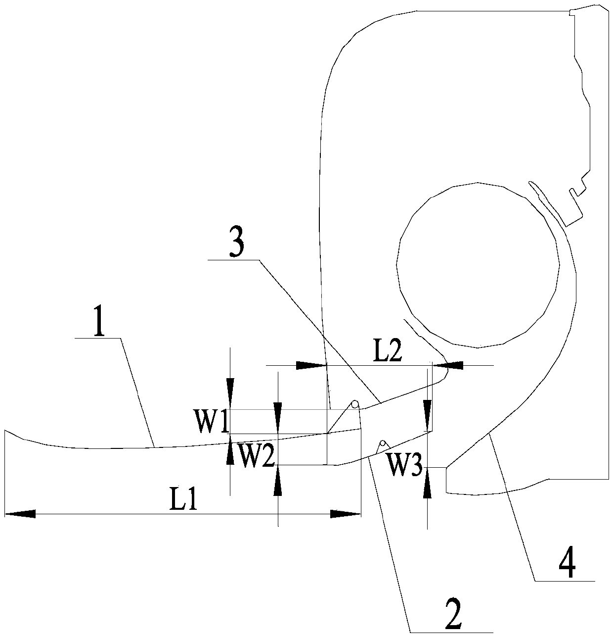
[0041] Such as figure 1 As shown, a wind deflector for a wall-mounted machine includes at least two wind deflector bodies arranged between the volute tongue flow guide wall 3 and the volute throat flow guide wall 4, the topmost wind deflector body and the volute tongue flow guide wall 3, between the adjacent air deflector bodies in the middle, and between the bottommost air deflector body and the cochlear throat deflector wall 4 are provided with air guide channels;

[0042] The lengths of the main bodies of the plurality of air deflectors gradually decrease along the direction from the volute tongue guide wall 3 to the cochlear throat guide wall 4, and the widths of the multiple air guide channels gradually increase along the direction from the volute tongue guide wall 3 to the volute throat guide wall 4 , the main body of the wind deflector is connected with a driving device, and the driving device is used to drive the main body of the wind deflector to rotate or translate. ...

Embodiment 2

[0049] A method for controlling the wind deflector of a wall-mounted machine, comprising the following steps:

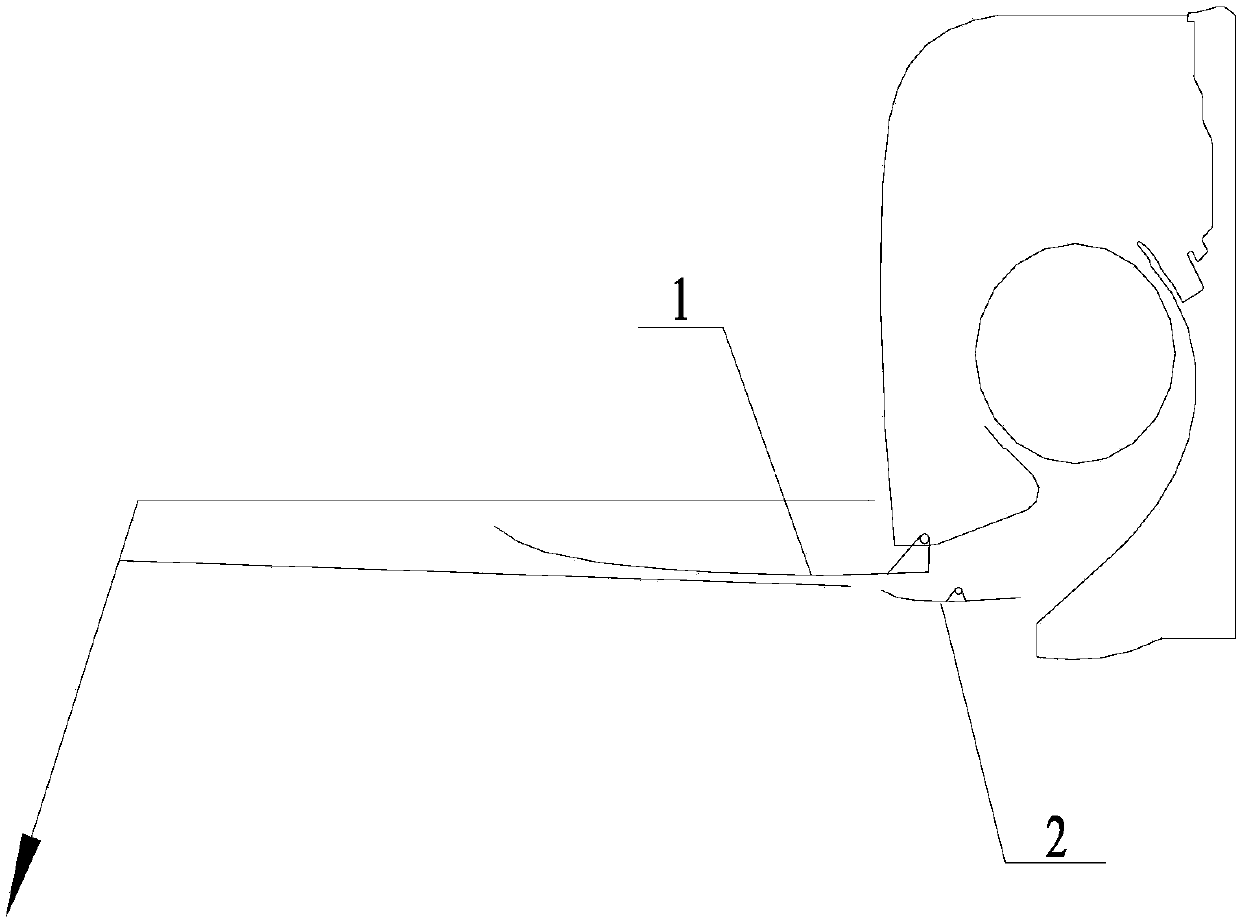
[0050] The driving device drives the main body of the air deflector to rotate or translate to adjust the width of the air guide channel, and then switch between different air supply modes. The air supply modes include global air supply, far-field air supply, mid-field or near-field air supply and extreme air supply. Ventilation nearby.

[0051] Among them, the global air supply mode supplies air to the entire space, the width of multiple air guide channels gradually increases along the direction from the volute tongue guide wall 3 to the cochlear throat guide wall 4, and the air supply direction of the air guide channels tends to be horizontal;

[0052]The far-field air supply mode is to supply air to a position farther away from the air outlet in the space. The outer end of the main body of the air deflector rises, and the distance between the inner end of the main ...

Embodiment 3

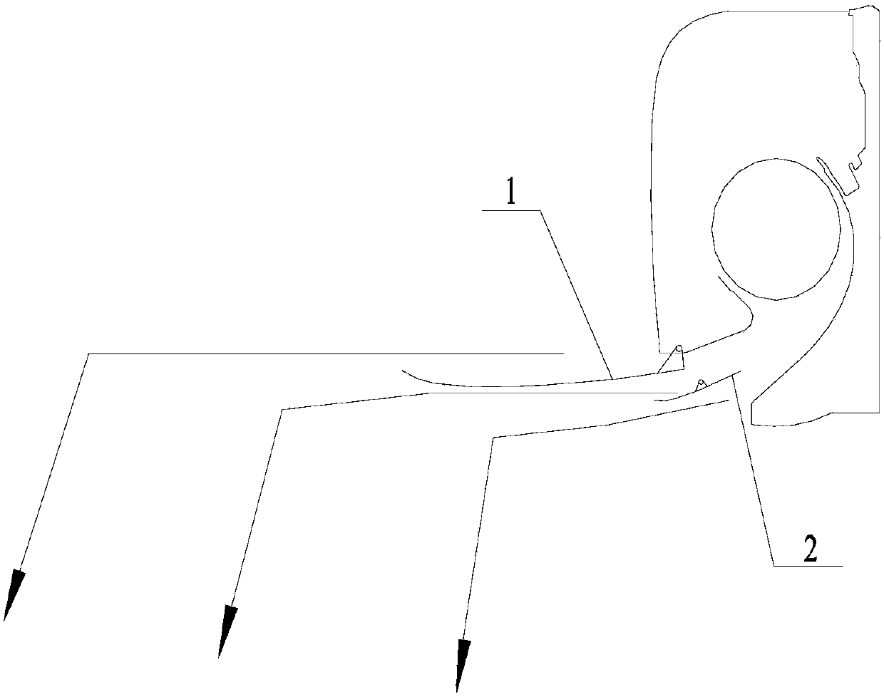
[0056] Such as figure 2 As shown, due to the air supply characteristics of cross-flow fan blades, the wind speed near the volute tongue at the air outlet is relatively high, and the first air deflector main body 1 mainly guides the wind in the high wind speed area, and the first air deflector main body 1 is the longest, and the high-speed area The distance between the first air deflector main body 1 and the second air deflector main body 2 is relatively large, which is a process of diffusion, which can further increase the wind speed, thereby sending the airflow to a very long distance above the sky and falling freely; And the length of the second air deflector main body 2 is relatively short, so the airflow in the wind speed area in the air outlet is sent to the sky above the midfield area and falls freely; the distance between the second air deflector main body 2 and the worm throat guide wall 4 is further increased, further The pressure is diffused, and the end of the volu...


PUM


Abstract

The invention relates to the technical field of wall-mounted air conditioners and particularly relates to a wall-mounted air conditioner air deflector, a regulating and controlling method thereof anda wall-mounted air conditioner. The wall-mounted air conditioner air deflector comprises at least two air deflector main bodies arranged between a volute tongue flow guiding wall and a volute throat flow guiding wall; the lengths of the air deflector main bodies decrease progressively in a direction from the volute tongue flow guiding wall to the volute throat flow guiding wall; the widths of a plurality of wind deflection passages decrease progressively in the direction from the volute tongue flow guiding wall to the volute throat flow guiding wall. The wall-mounted air conditioner air deflector provided by the invention has the beneficial effects that air at an air outlet is layered, air pressure is re-distributed, airflow from the same air outlet falls down at different distances in a room, so that the entire room is covered by airflow, and air does not blow people directly, improvement on both comfort and energy conservation is achieved, space adjustment of the air deflector main bodies is performed during a motion process, airflow pressurizing and depressurizing at the air outlet or air deflector superposition are achieved, and far field blowing, near field blowing and quick landing without heating air quantity attenuation are achieved.

Description

technical field [0001] The invention relates to the technical field of wall-mounted air conditioners, in particular to a wind deflector of a wall-mounted machine, a control method thereof, and a wall-mounted air conditioner. Background technique [0002] The wall-mounted air conditioner needs to be installed at a certain height. The air outlet of the body blows out cold / hot air to achieve cooling and heating of a certain space. Among them, in order to facilitate the adjustment of the air outlet direction, a wind deflector is installed at the air outlet of the body. Through Adjust the guide angle of the wind deflector, and then adjust the direction of the wind. [0003] At present, the air outlet of the air deflector of the wall-mounted air conditioner has a strong directivity, that is, when the far-field air is supplied, the position of the air deflector is horizontal or slightly raised; Blow down to the designated position. Among them, the strong directivity of the air ou...

Claims


Application Information

Patent Timeline
Patent Type & Authority Applications(China)
IPC IPC(8): F24F1/00F24F13/10F24F11/79
CPCF24F1/0011F24F13/10F24F13/1426F24F1/00F24F11/79F24F13/08Y02B30/70
Inventor 张辉王现林刘汉熊军高旭廖俊杰罗永前李树云周明
Owner GREE ELECTRIC APPLIANCES INC
Learn More