Self-circulation moisture removal temperature control type computer case
A computer and tide-dispelling technology, which is applied in the field of self-circulation tide-dispelling temperature-controlled computer cases, can solve the problems of single structure, unsatisfactory tide-dispelling heat dissipation effect, and easy-to-erode components, etc., and achieve the effect of comprehensive heat dissipation
- Summary
- Abstract
- Description
- Claims
- Application Information
AI Technical Summary
Problems solved by technology
Method used
Image
Examples
Embodiment 1
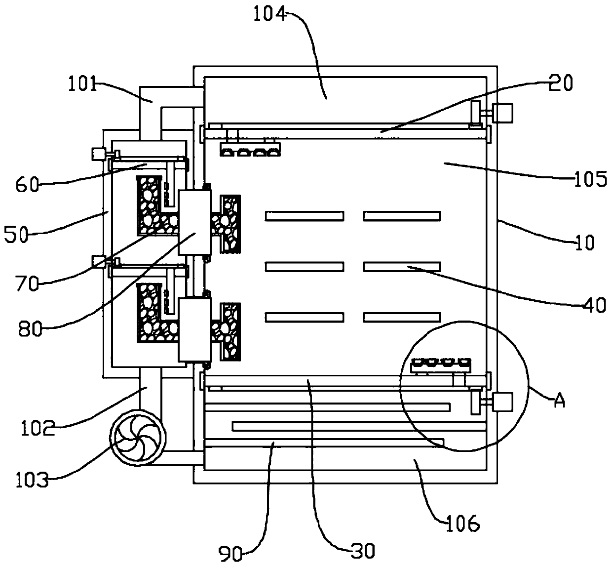
[0049] Such as figure 1 As shown, in the embodiment provided by the present invention, a self-circulation tide driving temperature control computer case, the self circulation tide driving temperature control computer case includes
[0050] Chassis 10;
[0051] an air suction part 20, the air suction part 20 is arranged in the upper inner cavity of the chassis 10;
[0052] A blowing part 30, the blowing part 30 is arranged in the lower inner cavity of the chassis 10;
[0053] A moisture-dispelling box 50, the moisture-dispelling box 50 is installed on one side of the chassis 10;
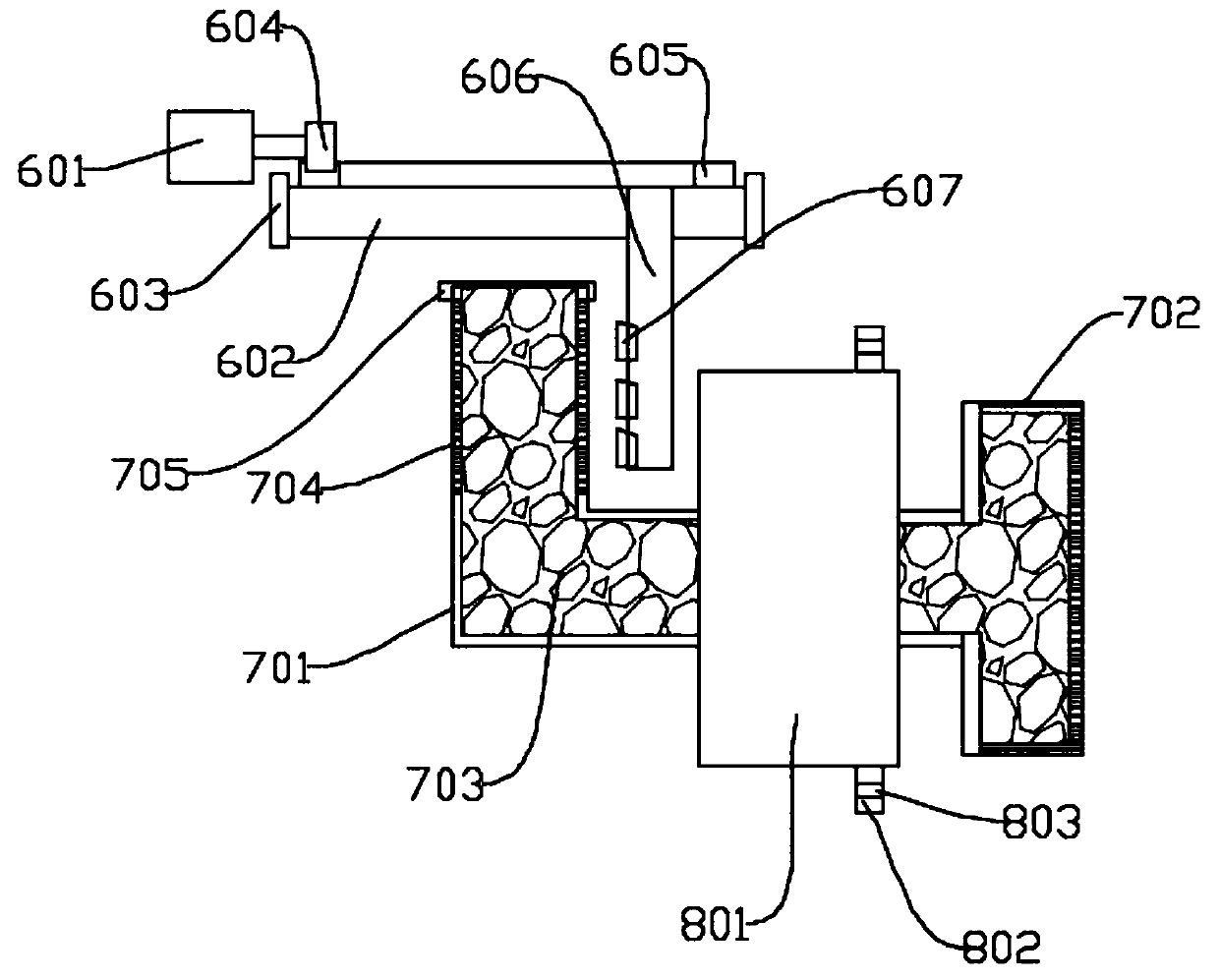
[0054] An air guide assembly 60, the air guide assembly 60 is arranged inside the air intake end of the moisture-dispelling box 50;
[0055] tide repelling assembly 70; and
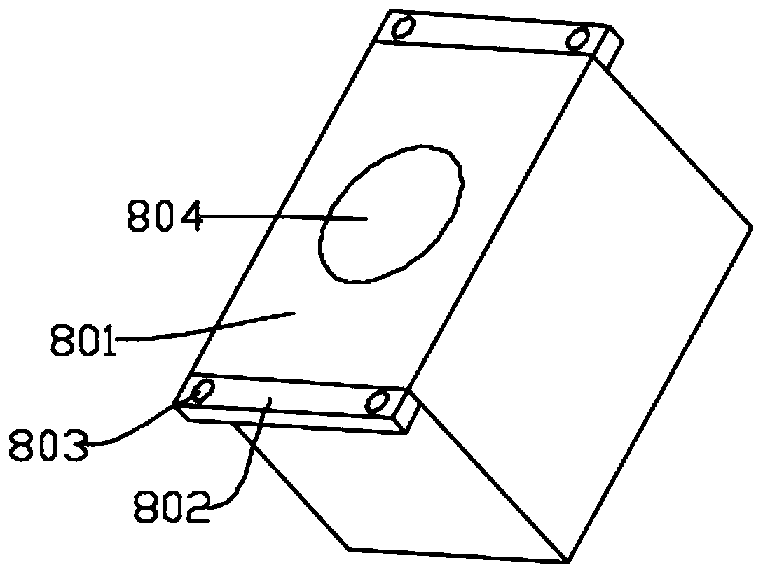
[0056] The installation assembly 80, the installation assembly 80 is fixedly installed on the partition between the chassis 10 and the moisture drive box 50; the moisture drive assembly 70 is fixedly installed on the installa...
Embodiment 2
[0061] Such as figure 1 As shown, in the embodiment provided by the present invention, a self-circulation tide driving temperature control computer case, the self circulation tide driving temperature control computer case includes
[0062] Chassis 10;
[0063] an air suction part 20, the air suction part 20 is arranged in the upper inner cavity of the chassis 10;
[0064] A blowing part 30, the blowing part 30 is arranged in the lower inner cavity of the chassis 10;
[0065] A moisture-dispelling box 50, the moisture-dispelling box 50 is installed on one side of the chassis 10;
[0066] An air guide assembly 60, the air guide assembly 60 is arranged inside the air intake end of the moisture-dispelling box 50;
[0067] tide repelling assembly 70; and
[0068] The installation assembly 80, the installation assembly 80 is fixedly installed on the partition between the chassis 10 and the moisture drive box 50; the moisture drive assembly 70 is fixedly installed on the installa...
Embodiment 3
[0076] Such as figure 1 As shown, in the embodiment provided by the present invention, a self-circulation tide driving temperature control computer case, the self circulation tide driving temperature control computer case includes
[0077] Chassis 10;
[0078] an air suction part 20, the air suction part 20 is arranged in the upper inner cavity of the chassis 10;
[0079] A blowing part 30, the blowing part 30 is arranged in the lower inner cavity of the chassis 10;
[0080] A moisture-dispelling box 50, the moisture-dispelling box 50 is installed on one side of the chassis 10;
[0081] An air guide assembly 60, the air guide assembly 60 is arranged inside the air intake end of the moisture-dispelling box 50;
[0082] tide repelling assembly 70; and
[0083] The installation assembly 80, the installation assembly 80 is fixedly installed on the partition between the chassis 10 and the moisture drive box 50; the moisture drive assembly 70 is fixedly installed on the installa...
PUM
 Abstract
Description
Claims
Application Information
 - R&D
- Intellectual Property
- Life Sciences
- Materials
- Tech Scout
- Unparalleled Data Quality
- Higher Quality Content
- 60% Fewer Hallucinations
Browse by: Latest US Patents, China's latest patents, Technical Efficacy Thesaurus, Application Domain, Technology Topic, Popular Technical Reports.
© 2025 PatSnap. All rights reserved.Legal|Privacy policy|Modern Slavery Act Transparency Statement|Sitemap|About US| Contact US: help@patsnap.com


