Film blowing machine

A technology of film blowing machine and servo motor, which is applied in the direction of removing smoke and dust, chemical instruments and methods, cleaning methods and utensils, etc., can solve the problems of time-consuming and laborious, machine idling, troublesome and troublesome cleaning, etc., to achieve high operation efficiency and ensure health and safety. , Easy to clean up

Inactive Publication Date: 2020-07-10
泉州宁遇新材料有限公司
View PDF0 Cites 0 Cited by
  • Summary
  • Abstract
  • Description
  • Claims
  • Application Information

AI Technical Summary

Problems solved by technology

[0003] Existing film blowing machines usually use manual feeding, which is time-consuming and labor-intensive, and it is easy to cause the machine to run idle due to uneven feeding. At the same time, the melting tank needs to be cleaned regularly during use, but due to its closed structure, it is very troublesome to clean up, so the present invention proposes a film blowing machine to solve the above problems

Method used


Image

  • Film blowing machine
  • Film blowing machine
  • Film blowing machine

Examples


Embodiment 1

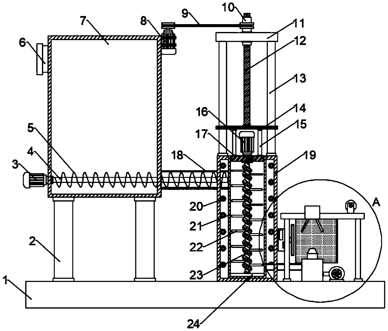
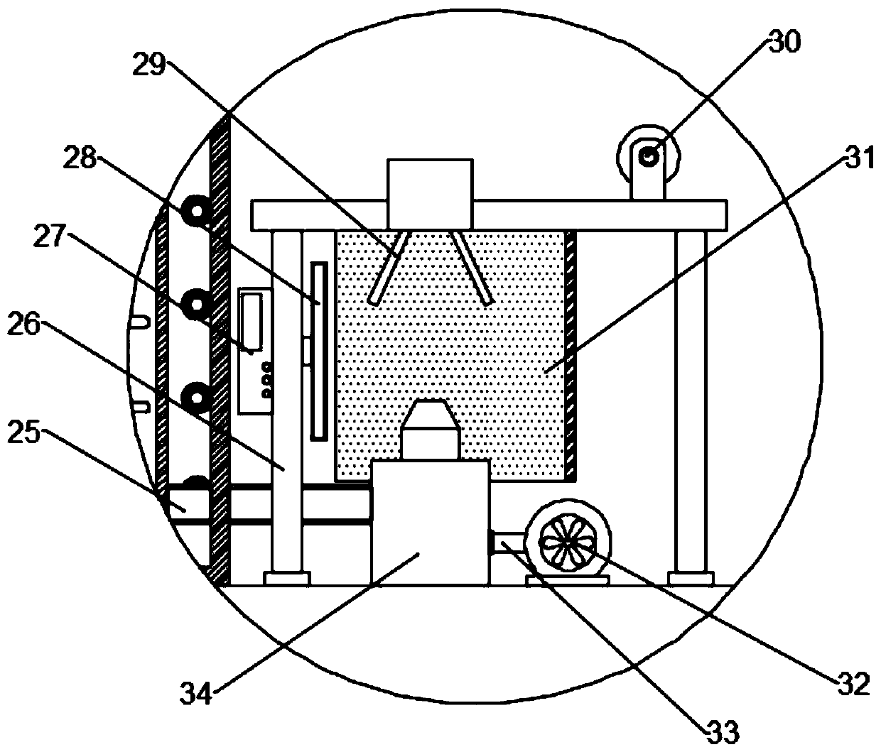
[0024] see figure 1 and figure 2 , in an embodiment of the present invention, a film blowing machine includes a base 1, a storage box 7 and a heating box 19, the storage box 7 is fixed above the base 1 through a plurality of first support rods 2, and the heating box 19 Fixed on the base 1, the upper part of the side wall of the material storage box 7 is provided with a material inlet 6, and a melting box 21 is fixed inside the heating box 19. The melting box 21 is made of metal material, and the side wall of the melting box 21 is provided with a thermal insulation layer, the annular cavity structure formed between the heating box 19 and the melting box 21 is evenly provided with an electromagnetic heating coil 20, and the lower part of the side wall of the material storage box 7 is provided with a material guide tube 18, and the material guide tube 18 is far away from the material storage box 7 One end of the rotating rod 4 extends into the melting tank 21, and the inner wal...

Embodiment 2

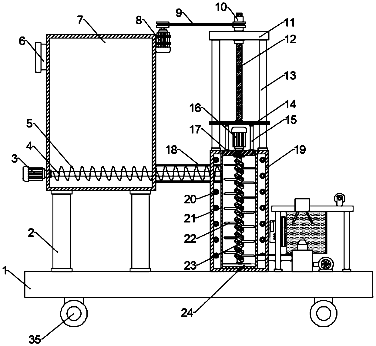
[0031] see image 3The difference between the embodiment of the present invention and embodiment 1 is that, further, in order to facilitate the movement of the device, the bottom of the base 1 is symmetrically provided with rollers 35, and the rollers 35 are self-locking rollers, and each roller 35 is provided with There is a brake assembly, and the staff can easily and conveniently move the device through the rollers 35, which saves time and effort, and is simple and practical.

[0032] The working principle of the present invention is: when the present invention is in use, first pour the plastic raw materials used to make the film into the storage box 7, and then start the first servo motor 3, the third servo motor 16 and the electromagnetic heating The coil 20, the first servo motor 3 drives the rotating rod 4 to rotate so that the screw blade 5 evenly transports the plastic raw materials in the storage box 7 to the melting tank 21 for melting, and the third servo motor 16 ...


PUM


Abstract

The invention discloses a film blowing machine. The film blowing machine comprises a base, a storage box and a heating box, wherein the storage box is fixed to a position above the base through a plurality of first supporting rods; the heating box is fixedly arranged on the base; a fusion box is fixedly arranged in the heating box; a rotating rod is rotatably arranged on the inner wall of the storage box; one end, close the heating box, of the rotating rod extends into a guide pipe; spiral blades are arranged on the rotating rod; a cover plate is detachably arranged on the upper part of the fusion box; a screw rod is rotatably arranged at the bottom of the cover through a bearing; the lower end of the screw rod extends to the bottom of an inner cavity of the fusion box; a scraper is rotatably arranged on the lower end of the screw rod; two supporting rods are symmetrically arranged at the top of the heating box; a rectangle plate is fixedly arranged between the tops of the two supporting rods; an internal thread rotating cylinder is rotatably arranged on the rectangle plate in a penetrating mode; and a forming support, an air compressor and a mold head are fixedly arranged on the base. The film blowing machine can mechanically feed in a uniform speed so as to be prevented from idling and has higher operational efficiency; and meanwhile, the fusion box is convenient and rapid toclean, simple and trouble-saving, so that the film blowing machine has very high practicability.

Description

technical field [0001] The invention relates to the technical field of film material production devices, in particular to a film blowing machine. Background technique [0002] Blown film is a plastic processing method, which means that the molten material plasticized by the extruder barrel is extruded through the forming mold to support the round-shaped film blank, and then blows air with a certain pressure into the barrel to blow the cylindrical film The blank plastic is inflated to meet the production requirements of the diameter and thickness of the film tube, and is cooled and shaped into a film product. This kind of blown film is generally produced with polyethylene, polypropylene and polyvinyl chloride resin. The film formed by blown film has color and luster. Well-proportioned, clean, and good stretchability of the finished product, therefore, film blowing machines are widely used in the industry. [0003] Existing film blowing machines usually use manual feeding, wh...

Claims


Application Information

Patent Timeline
Patent Type & Authority Applications(China)
IPC IPC(8): B29C55/28B29C48/00B29C48/285B08B15/04B29C48/27B29C48/80B29C48/88B29C48/28
CPCB08B15/04B29C48/0018B29C48/27B29C48/2715B29C48/28B29C48/285B29C48/298B29C48/832B29C48/88B29C55/28
Inventor 林燕
Owner 泉州宁遇新材料有限公司
Why Eureka
Try Eureka