Oil separation device, condenser and refrigeration equipment

A refrigeration device and oil separation technology, applied in the direction of evaporator/condenser, refrigerator, refrigeration components, etc., can solve the problems that the reliability of oil return cannot be guaranteed, and the oil return pipe cannot always fully contact the liquid surface, etc., so as to ensure oil return reliability effect

Pending Publication Date: 2018-04-20
GREE ELECTRIC APPLIANCES INC
View PDF6 Cites 0 Cited by
  • Summary
  • Abstract
  • Description
  • Claims
  • Application Information

AI Technical Summary

Problems solved by technology

[0004] The existing oil separation device uses oil return on both sides, and there is a gap between the oil baffle plate on the side of the oil return port and the oil separation shell, and the gas on the upper part of the oil baffle plate will impact the liquid level at the oil return port, so that the oil return pipe cannot always be fully filled. In contact with the liquid surface, the oil return reliability cannot be guaranteed

Method used


Image

  • Oil separation device, condenser and refrigeration equipment
  • Oil separation device, condenser and refrigeration equipment
  • Oil separation device, condenser and refrigeration equipment

Examples


Embodiment Construction

[0027] The technical solutions of the present invention will be described in further detail below with reference to the accompanying drawings and embodiments.

[0028] The specific embodiments of the present invention are for the convenience of further description of the concept of the present invention, the technical problems to be solved, the technical features constituting the technical solution and the technical effects brought about. It should be noted that the description of these embodiments does not constitute a limitation of the present invention. In addition, the technical features involved in the embodiments of the present invention described below may be combined with each other as long as they do not conflict with each other.

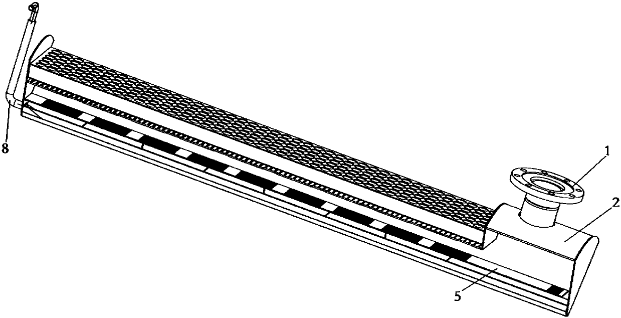
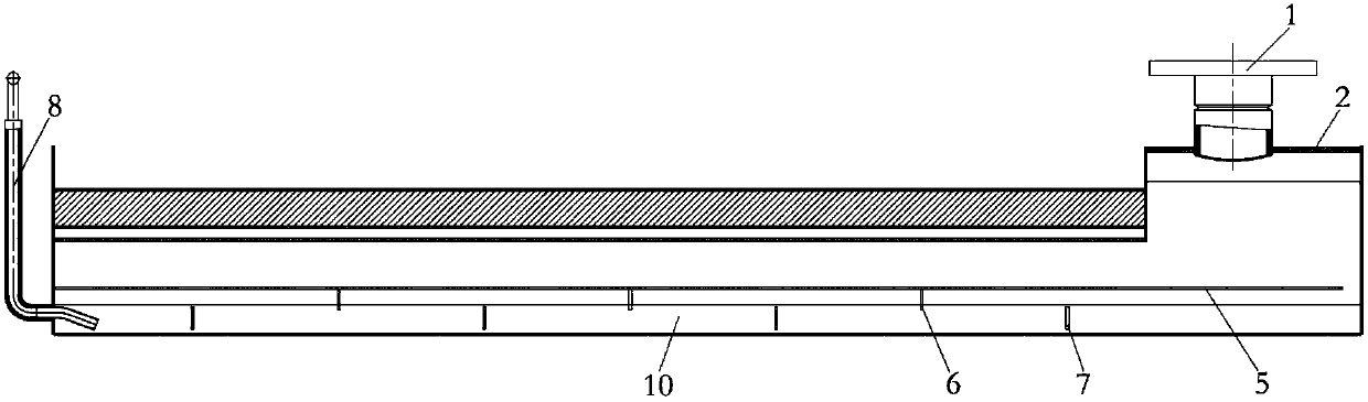
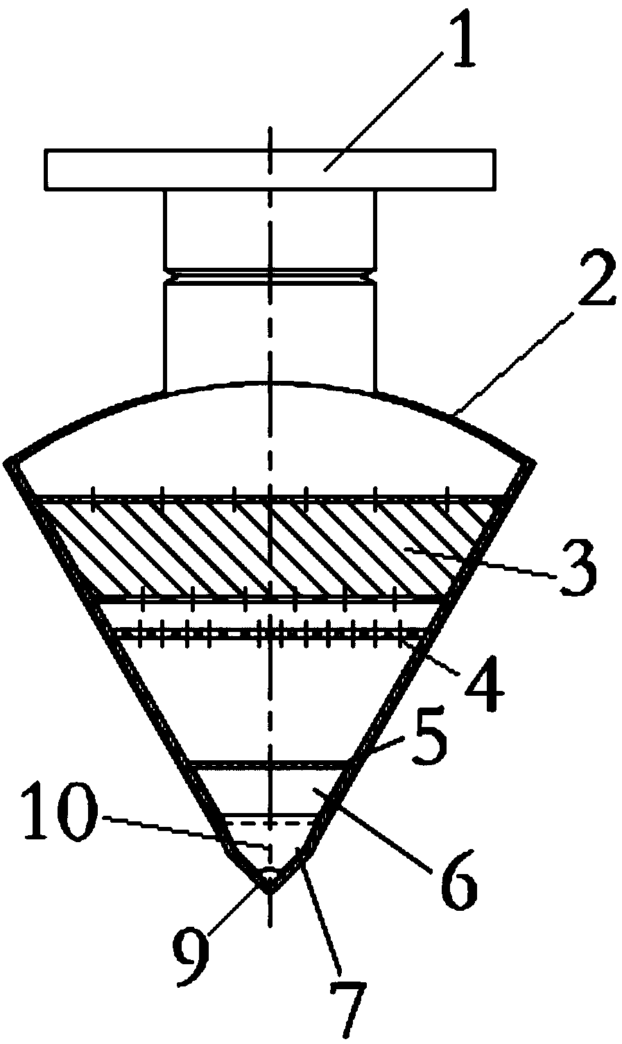
[0029] In a schematic or specific embodiment of the oil separation device of the present invention, such as figure 1 and figure 2 As shown, the oil separation device includes an oil separation shell 2, a gas-liquid filter 3, an equalizer...


PUM


Abstract

The invention relates to an oil separation device, a condenser and refrigeration equipment. The oil separation device comprises an oil separation shell, an oil stopping plate and an oil return openingfor discharging out oil, an oil return groove is formed in the bottom of the oil separation shell, the oil stopping plate is arranged in the oil separation shell and located above the oil return groove, and the end, close to the oil return opening, of the oil stopping plate is in sealed connection with the oil separation shell. The oil stopping plate on one side of the oil returning opening is insealed connection, and therefore gas at the upper portion is prevented from impacting the liquid face of the oil returning opening, it is guaranteed that an oil return pipe can be in sufficient contact with the liquid face all the time, and oil return reliability can be guaranteed.

Description

technical field [0001] The invention relates to the technical field of refrigeration, in particular to an oil separation device, a condenser and a refrigeration device. Background technique [0002] As one of the four major components of the water-cooled screw unit, the condenser is used to condense the high-temperature and high-pressure gaseous refrigerant discharged from the compressor into a high-pressure medium-temperature liquid refrigerant in the refrigeration cycle. In the actual operation of the unit, in addition to the high-temperature and high-pressure gas-liquid mixed refrigerant discharged from the compressor, the condenser also carries a large amount of lubricating oil. If this part of lubricating oil accumulates in the condenser and is not separated and returned to the compressor, it will not only weaken the heat transfer capacity of the condenser, but also cause damage to the compressor due to lack of lubricating oil lubrication, and the system cannot continue...

Claims


Application Information

Patent Timeline
Patent Type & Authority Applications(China)
IPC IPC(8): F25B39/04F25B43/02
CPCF25B39/04F25B43/02
Inventor 陈增辉王铁强马严杨旭峰
Owner GREE ELECTRIC APPLIANCES INC
Why Eureka
Try Eureka