Cable monitoring equipment and method

A technology for monitoring equipment and cables, applied in radio wave measurement systems, satellite radio beacon positioning systems, measurement devices, etc., can solve problems such as insecure operation of cables, and achieve the effect of ensuring safe operation

Inactive Publication Date: 2018-04-20
STATE GRID BEIJING ELECTRIC POWER +1
View PDF7 Cites 4 Cited by
  • Summary
  • Abstract
  • Description
  • Claims
  • Application Information

AI Technical Summary

Problems solved by technology

[0010] The embodiment of the present invention provides a cable monitoring device and method to at least solve the t

Method used


Image

  • Cable monitoring equipment and method
  • Cable monitoring equipment and method
  • Cable monitoring equipment and method

Examples


Example Embodiment

[0028] In order to enable those skilled in the art to better understand the solutions of the present invention, the technical solutions in the embodiments of the present invention will be described clearly and completely with reference to the accompanying drawings in the embodiments of the present invention. Obviously, the described embodiments are only It is a part of the embodiments of the present invention, not all the embodiments. Based on the embodiments of the present invention, all other embodiments obtained by those of ordinary skill in the art without creative work shall fall within the protection scope of the present invention.

[0029] It should be noted that the terms "first" and "second" in the specification and claims of the present invention and the above-mentioned drawings are used to distinguish similar objects, and not necessarily used to describe a specific sequence or sequence. It should be understood that the data used in this way can be interchanged under ap...


PUM


Abstract

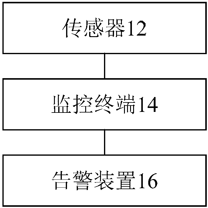
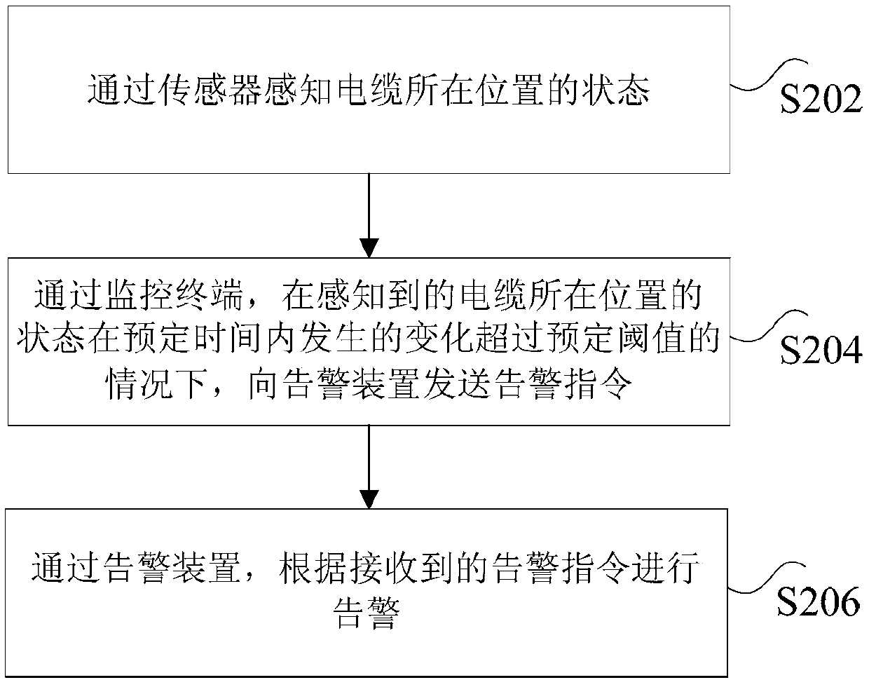
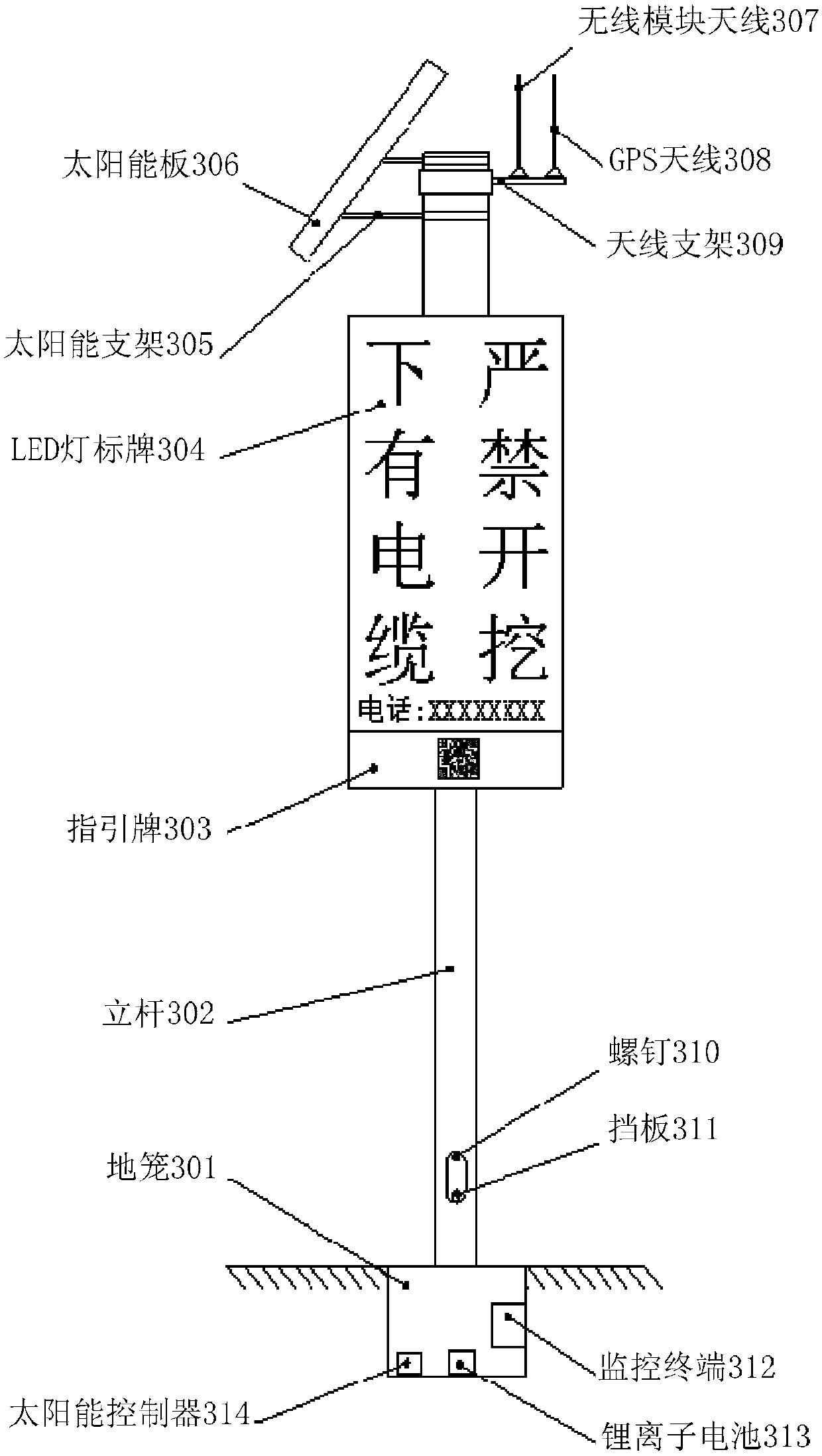
The invention discloses cable monitoring equipment and a cable monitoring method. The cable monitoring equipment comprises a sensor, a monitoring terminal and an alarm device, wherein the sensor is used for sensing the position state of a cable; the monitoring terminal is connected with the sensor through a sensor interface, and sends an alarm instruction to the alarm device under the circumstancethat change of the sensed position state of the cable exceeds a predetermined threshold within a predetermined time; the alarm device is communicated with the monitoring terminal, and alarms based onthe received alarm instruction. Through the cable monitoring equipment and the cable monitoring method, the technical problems that in the related art, safe operation of the cable cannot be guaranteed due to no later monitoring is solved.

Description

technical field [0001] The invention relates to the application field of power equipment, in particular to a cable monitoring equipment and method. Background technique [0002] With the expansion of city scale and the continuous improvement of urban environment, the impact of overhead lines on urban landscape and space is becoming more and more obvious. In order to make the urban environment beautiful and rational use of urban space, but also in order to ensure the safety of various facilities and personal safety, the use of buried cables for transmission lines has become one of the very important measures. [0003] For a long time, cable laying mainly adopts direct burial, pipe arrangement, cable trench and power tunnel, etc.: [0004] Direct burial laying does not require any external protection structures, and the cables are directly buried in the underground soil. It is suitable for the same path with fewer pipelines, infrequent excavation, and no underground corrosion...

Claims


Application Information

Patent Timeline
IPC IPC(8): G01C21/18G01S19/01
CPCG01C21/18G01S19/01
Inventor 刘皓闫春江李光张成史海波李譞高智益蔡松涛林一轩
Owner STATE GRID BEIJING ELECTRIC POWER
Why Eureka
Try Eureka