
Wireless early warning device of transformer substation

A technology of early warning devices and substations, applied in the field of substations, can solve problems such as unreliability, long time delay, and high cost of signal monitoring, and achieve the effect of low cost and safe operation

Inactive Publication Date: 2011-07-06
上海申瑞电力科技股份有限公司
View PDF0 Cites 2 Cited by
  • Summary
  • Abstract
  • Description
  • Claims
  • Application Information

AI Technical Summary

Problems solved by technology

[0002] The signal monitoring of the existing substations is operated through the local background or dispatching, so the signal alarms are all sent up through layers, and can only be reported to the superior level by level when someone is on duty. Restricted by human factors, real-time performance has the disadvantages of low efficiency, long delay, and unreliability, and it is easy to cause losses to users due to missing the best troubleshooting time
[0003] In addition, traditional signal monitoring requires a large number of peripheral equipment, such as communication equipment, monitoring equipment, alarm equipment, etc., so the cost of signal monitoring is very high, and all equipment must be under normal and reliable operating conditions to correctly detect fault signals. With so many devices, it is inevitable that various accidents will occur, which will bring uncertain factors to the actual signal monitoring of the power station and hidden dangers to the safe operation of the substation.

Method used


Image

  • Wireless early warning device of transformer substation
  • Wireless early warning device of transformer substation
  • Wireless early warning device of transformer substation

Examples


Embodiment Construction

[0018] The embodiments of the present invention will be described in further detail below in conjunction with the accompanying drawings, but the present embodiments are not intended to limit the present invention, and any similar structures and similar changes of the present invention should be included in the protection scope of the present invention.

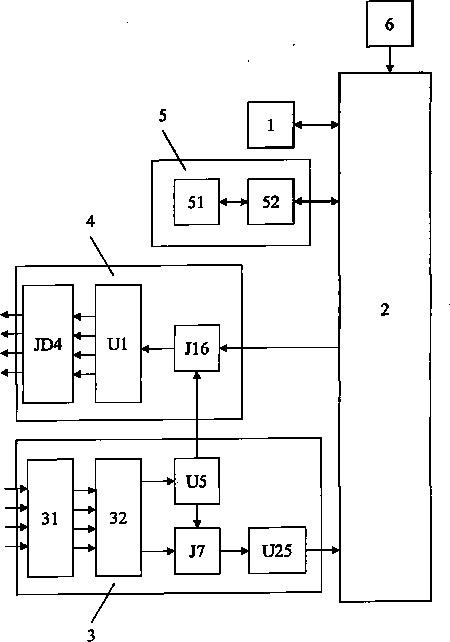
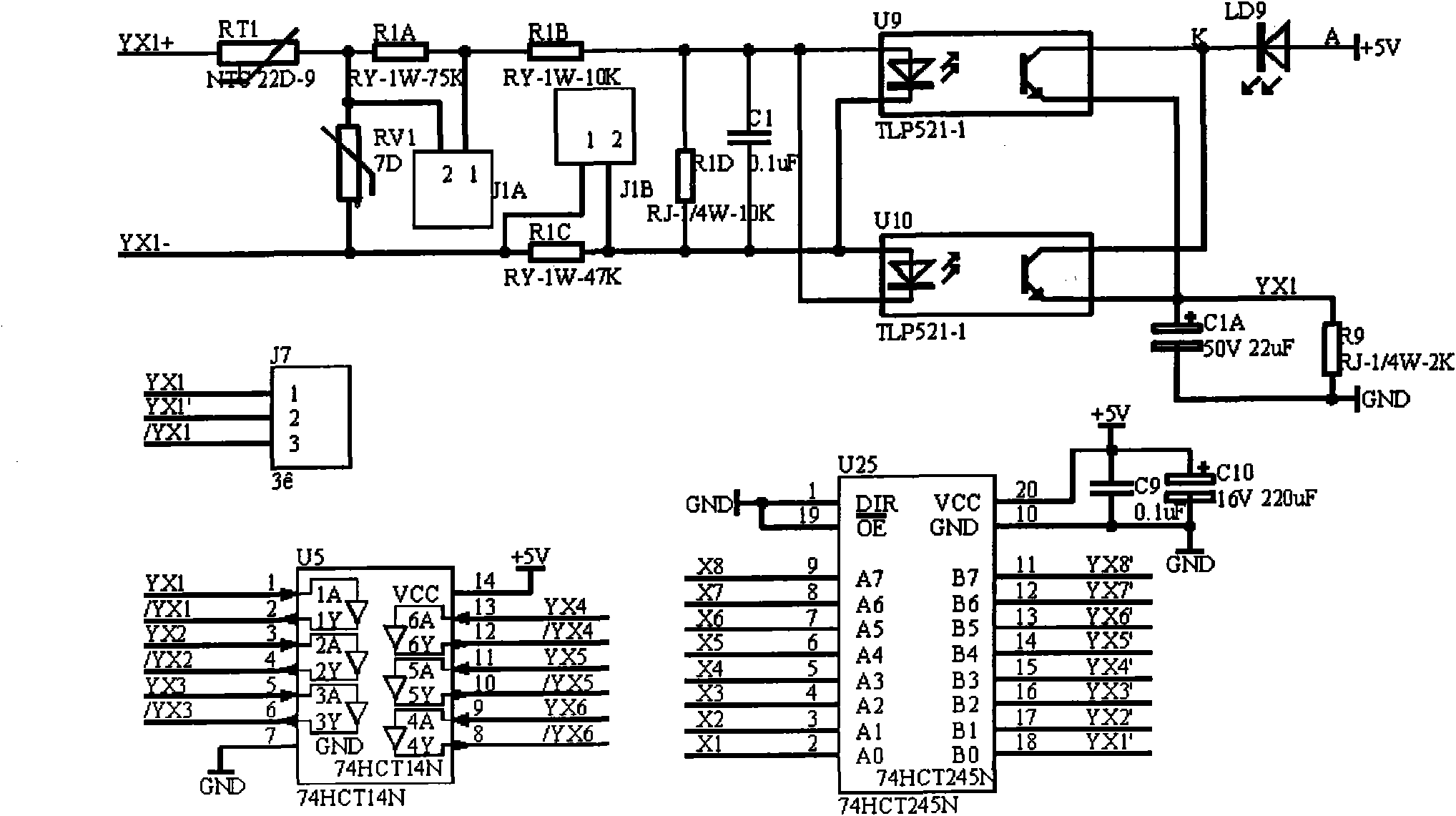
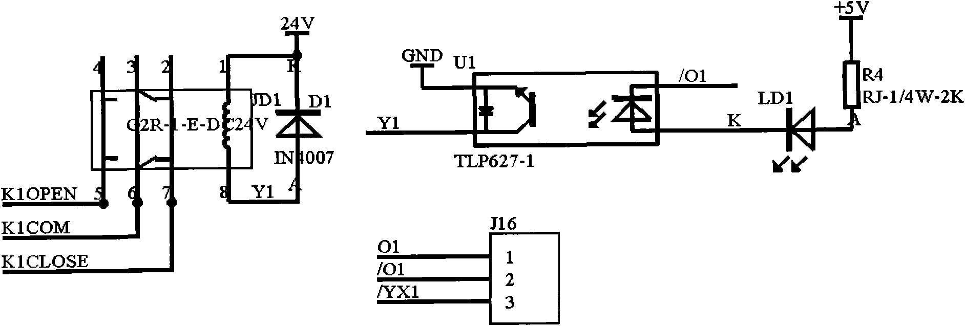
[0019] Such as figure 1 As shown, a substation wireless early warning device provided by the embodiment of the present invention is characterized in that it includes at least one mobile phone 1, a GSM short message sending and receiving control unit 2, and a photoelectric isolation binary input unit 3 for collecting substation binary input signals , the output relay unit 4 used to control the action actuator of the substation, the line serial communication isolation unit 5 used to interconnect the GSM short message sending and receiving control unit with external equipment, the system status indicating unit 6 used to indicate t...


PUM


Abstract

The invention discloses a wireless early warning device of a transformer substation, which relates to the technical field of transformer stations and solves the technical problem of resolving faults of the transformer substation immediately. The wireless early warning device comprises a mobile phone, a GSM (Global System For Mobile Communication) short message transceiving control unit, a photoelectric isolation input unit, an output relay unit, a serial communication isolation unit, a system state indicating unit, and a switching power unit, wherein the photoelectric isolation input unit is used for collecting input signals of the transformer substation, the output relay unit is used for controlling an action execution mechanism of the transformer substation, the serial communication isolation unit is used for connecting the GSM short message transceiving control unit with external equipment, the system state indicating unit is used for indicating the system running state, the switching power unit is used for supplying power for all the units, and the mobile phone is used for receiving an early warning signal or sending a control instruction of the GSM short message transceiving control unit; and the GSM short message transceiving control unit collects and detects an input signal of the transformer substation through the photoelectric isolation input unit, and controls the action execution mechanism of the transformer substation through the input relay unit. The wireless early warning device can monitor and maintain the transformer substation remotely.

Description

technical field [0001] The invention relates to the technology of a substation, in particular to a technology of a wireless early warning device for a substation. Background technique [0002] The signal monitoring of the existing substations is operated through the local background or dispatching, so the signal alarms are all sent up through layers, and can only be reported to the superior level by level when someone is on duty. Restricted by human factors, real-time performance has the disadvantages of low efficiency, long delay, and unreliability. It is easy to cause losses to users due to missing the best troubleshooting time. [0003] In addition, traditional signal monitoring requires a large number of peripheral equipment, such as communication equipment, monitoring equipment, alarm equipment, etc., so the cost of signal monitoring is very high, and all equipment must be under normal and reliable operating conditions to correctly detect fault signals. With so many de...

Claims


Application Information

Patent Timeline
IPC IPC(8): H02J13/00G08B25/10
CPCY04S40/126Y02B90/2661Y04S40/127Y02B90/2653Y02B90/20
Inventor 周文华
Owner 上海申瑞电力科技股份有限公司
Learn More