Friction wear test machine

A friction and wear test, frame technology, applied in the direction of testing wear resistance, etc., can solve the problems of jumping phenomenon, pressure can not be adjusted, affecting observation, etc., to avoid jumping, accurate test results, and reduce investment costs.

Active Publication Date: 2018-04-20
LUOYANG INST OF SCI & TECH
View PDF22 Cites 7 Cited by
  • Summary
  • Abstract
  • Description
  • Claims
  • Application Information

AI Technical Summary

Problems solved by technology

[0003] In the process of simulating the cutting state between the tool and the base material through the existing friction test equipment, on the one hand, the pressure between the base material and the tool cannot be adjusted, and it is impossible to simulate the different pressures between the tool and the base material On the other hand, due to the limitation of process precision, there are more or less uneven concave-convex surfaces on the tool and the substrate sample, so that when the tool sample and the substrate sample are in high-speed relative rotation Jumping phenomenon occurs, which affects the observation of the final test result

Method used


Image

  • Friction wear test machine
  • Friction wear test machine
  • Friction wear test machine

Examples


Embodiment Construction

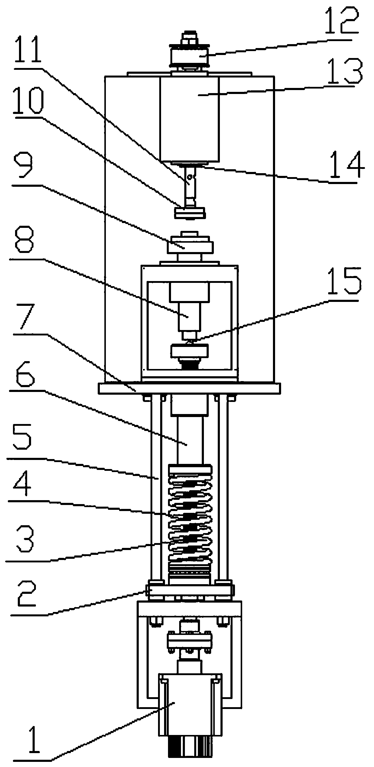
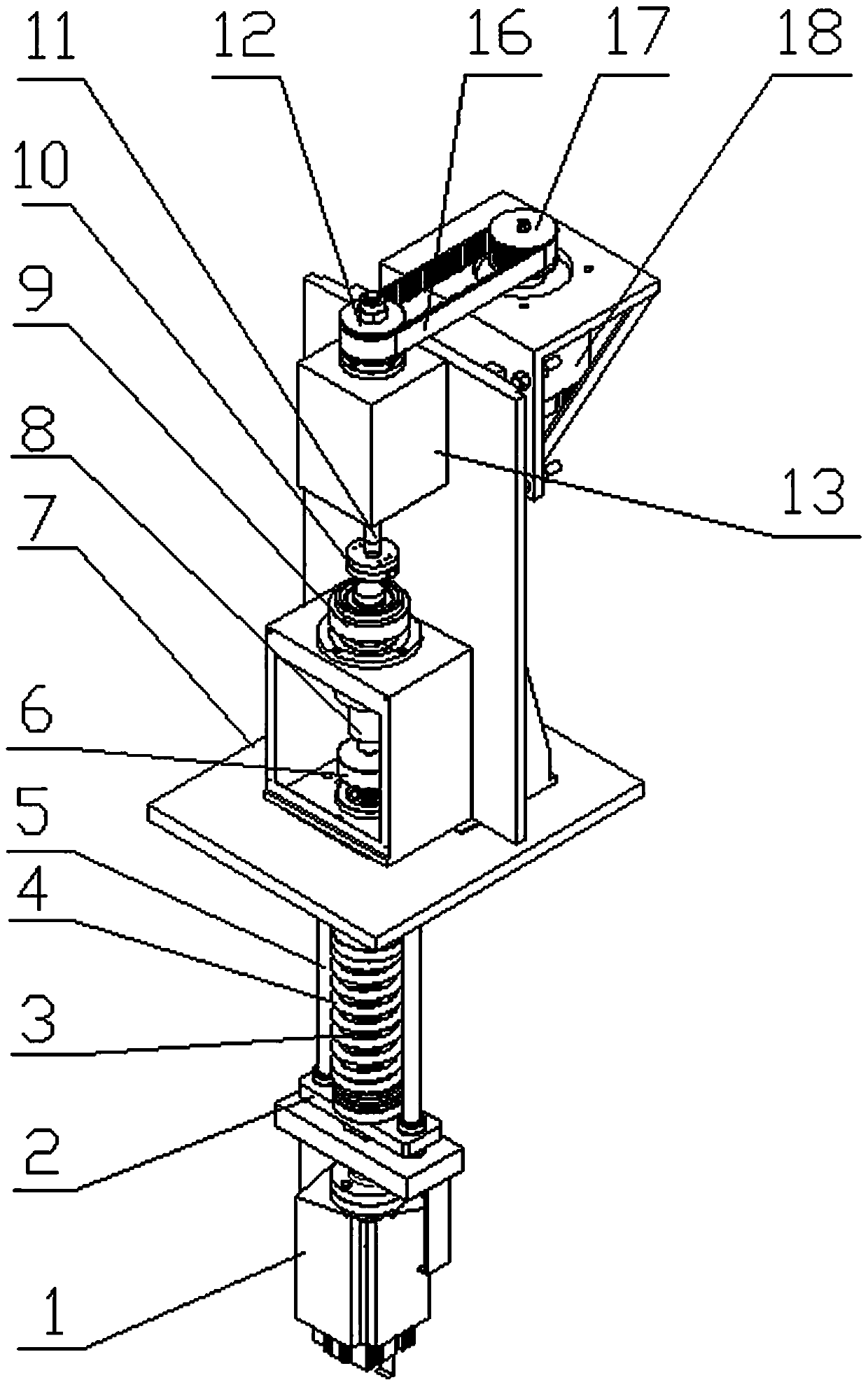
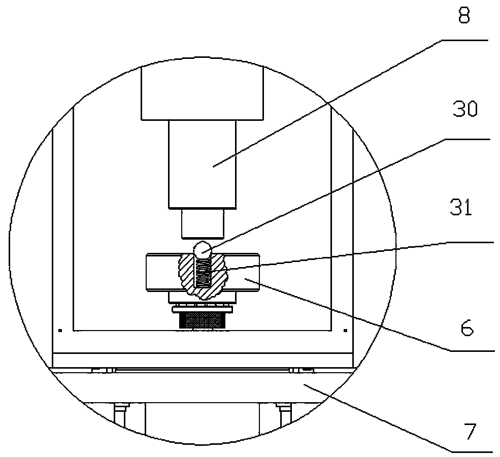
[0029] like Figure 1 to Figure 9 As shown, a friction and wear testing machine of the present invention includes a frame 7 and a rotating shaft 11 and a lifting shaft 8 coaxially arranged on the frame 7 along the vertical direction. The rotary shaft 11 is driven to rotate by the rotary drive device arranged on the frame 7, and the tool sample holder 10 for fixing the tool sample is connected to the lower end of the rotary shaft 11 through a movable interface, and then the tool sample holder is driven by the rotary drive device The tool sample on 10 rotates at high speed. The elevating shaft 8 drives up and down through the elevating driving device arranged on the frame 7, and the frame 7 is provided with an axle sleeve for the elevating shaft 8 to lift and slide, and the elevating shaft 8 and the axle sleeve are installed through spline fit, ensuring This prevents the lifting shaft 8 from rotating on the premise that the lifting shaft 8 can lift and slide in the axle sleeve....


PUM


Abstract

The invention relates to the field of friction test devices, and concretely relates to a friction wear test machine. The friction wear test machine comprises a frame, and a rotating shaft and a lifting shaft which are coaxially arranged on the frame along a vertical direction, the rotating shaft is driven by a rotation driving device arranged on the frame to rotate, the lower end of the rotating shaft is connected with a cutter sample clamp for fixing a cutter sample through a movable interface, the lifting shaft is driven by a lifting driving device arranged on the frame to lift, an elastic connecting piece is arranged between the lifting shaft and the lifting driving device, and a substrate sample clamp for fixing a substrate sample is arranged at the upper end of the lifting shaft. Thefriction wear test machine can accurately control a pressure between the cutter sample and the substrate sample and overcome bounce of the cutter sample and the substrate sample, caused by poor processing precision, and can easily carry out friction wear test in multiple forms.

Description

technical field [0001] The invention relates to the field of friction testing equipment, in particular to a friction and wear testing machine. Background technique [0002] In the field of lathe cutting, the friction between the tool and the base material can easily lead to tool damage, and the cutting surface of the base material is too rough to meet the technical requirements. Generally, it is necessary to use a friction test to determine which material the tool is most suitable for cutting a certain substrate, or what kind of lubricating oil is used to reduce the friction between the tool and the substrate during the cutting process. [0003] In the process of simulating the cutting state between the tool and the base material through the existing friction test equipment, on the one hand, the pressure between the base material and the tool cannot be adjusted, and it is impossible to simulate the different pressures between the tool and the base material On the other hand...

Claims


Application Information

Patent Timeline
Patent Type & Authority Applications(China)
IPC IPC(8): G01N3/56
CPCG01N3/56
Inventor 李彬王红刘建寿赵振法
Owner LUOYANG INST OF SCI & TECH
Why Eureka
Try Eureka