Multi-scale calibration plate
A calibration board, multi-scale technology, applied in the field of computer vision, can solve the problems of increasing development and maintenance costs, hardware costs, etc., to achieve the effect of saving hardware costs and development and maintenance costs, and avoiding calibration errors
- Summary
- Abstract
- Description
- Claims
- Application Information
AI Technical Summary
Problems solved by technology
Method used
Image
Examples
Embodiment 1
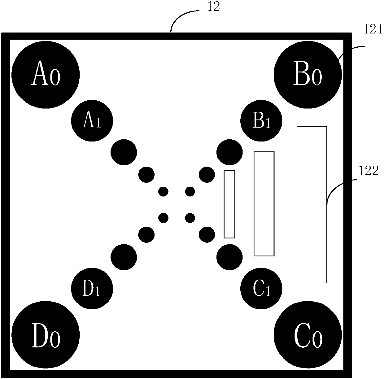
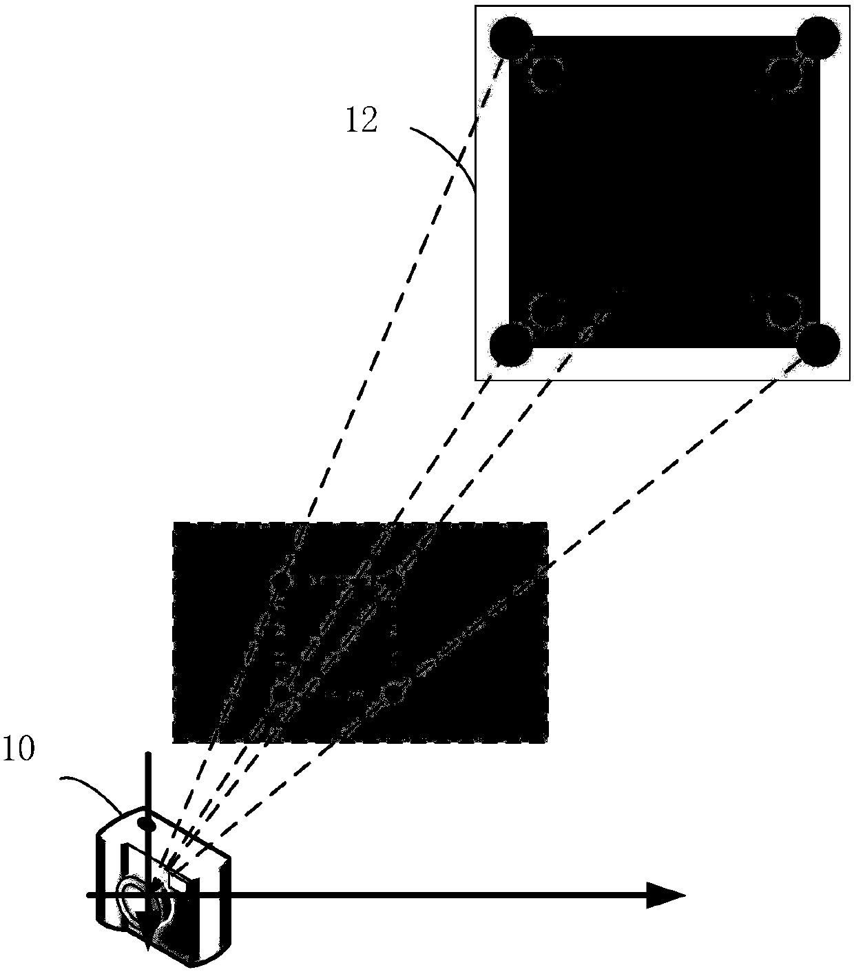
[0036] figure 1 A schematic distribution diagram of a multi-scale calibration plate provided by an embodiment of the present invention is shown. The surface of the multi-scale calibration plate 12 is provided with at least two groups of calibration base points 121 and identifiable codes 122 .
[0037] Each set of calibration base points 121 includes at least three identical calibration points distributed in an orthogonal relationship. In this embodiment, each group of calibration base points is described by taking four calibration points in an orthogonal relationship as an example. In other embodiments of the present invention, each group of calibration base points may also include three or more than four calibration points in an orthogonal relationship formed by connecting the center points of the calibration points at any angle as an example for illustration.
[0038] Define the first group of calibration base points as a group of calibration base points near the edge of t...
Embodiment 2
[0084] Figure 4 A schematic structural diagram of a multi-scale calibration plate provided by the second embodiment of the present invention is shown.
[0085] The multi-scale calibration plate 12 includes: calibration points 121 for calibrating the calibration parameters of the imaging device; codes 122 for identifying the corresponding physical distances, including: code start bit 123 , code end bit 124 and code bit 125 .
[0086] In this embodiment, the image data of the multi-scale calibration plate acquired by imaging devices with three different fields of view is taken as an example for illustration. The field of view of the computer vision system may be of any size, not limited to the three types in this embodiment. A set of calibration base points with the largest area corresponding to different field of view image data is different. For example, in the field of view Rect0, after filtering interference points, edge adhesion areas and non-connected areas, a set of calibr...
Embodiment 3
[0109] Figure 6 A schematic structural diagram of a multi-scale calibration plate provided by the third embodiment of the present invention is shown.
[0110] In this embodiment, each set of calibration base points includes three identical calibration points 121 whose center points are connected to a line in an orthogonal relationship. The calibration points 121 are circles filled with black. The code 122 is set between two calibration points in each group of calibration base points in an orthogonal relationship, and is used to identify the physical distance between the two corresponding calibration points. The codes of each group of calibration base points are the same, and the codes of each group of calibration base points are different from each other. For example, in the field of view Rect0, after filtering the interference points and connected areas, the obtained set of calibration base points with the largest area is A0, B0, and C0, where the codes between A0B0 and A0C...
PUM
 Abstract
Description
Claims
Application Information
 - R&D
- Intellectual Property
- Life Sciences
- Materials
- Tech Scout
- Unparalleled Data Quality
- Higher Quality Content
- 60% Fewer Hallucinations
Browse by: Latest US Patents, China's latest patents, Technical Efficacy Thesaurus, Application Domain, Technology Topic, Popular Technical Reports.
© 2025 PatSnap. All rights reserved.Legal|Privacy policy|Modern Slavery Act Transparency Statement|Sitemap|About US| Contact US: help@patsnap.com


