Magnetic ring winding machine having positioning function

A technology of winding wire and function, applied in the field of magnetic winding machine, can solve the problems that the magnetic winding wheel cannot be installed stably, the winding tightness cannot be adjusted, and the winding end cannot be reminded in time.

Active Publication Date: 2018-04-20
惠州市瑞恺电子有限公司
View PDF7 Cites 4 Cited by
  • Summary
  • Abstract
  • Description
  • Claims
  • Application Information

AI Technical Summary

Problems solved by technology

The winding mechanism greatly improves the hooking accuracy of the winding machine, reduces the failure rate of the equipment, and improves the production efficienc

Method used


Image

  • Magnetic ring winding machine having positioning function
  • Magnetic ring winding machine having positioning function
  • Magnetic ring winding machine having positioning function

Examples


Embodiment Construction

[0023] The following will clearly and completely describe the technical solutions in the embodiments of the present invention with reference to the accompanying drawings in the embodiments of the present invention. Obviously, the described embodiments are only some, not all, embodiments of the present invention.

[0024] Example.

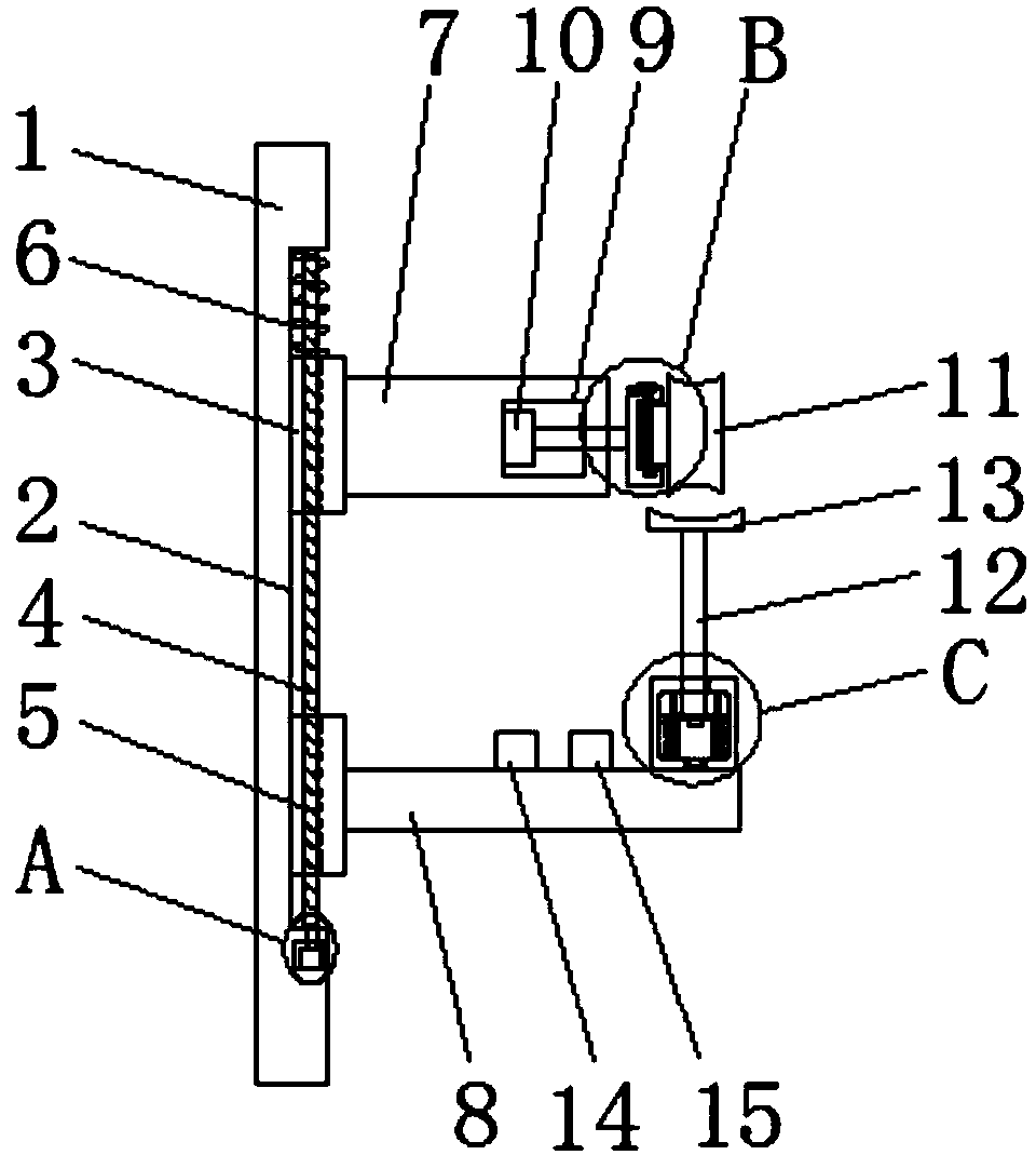
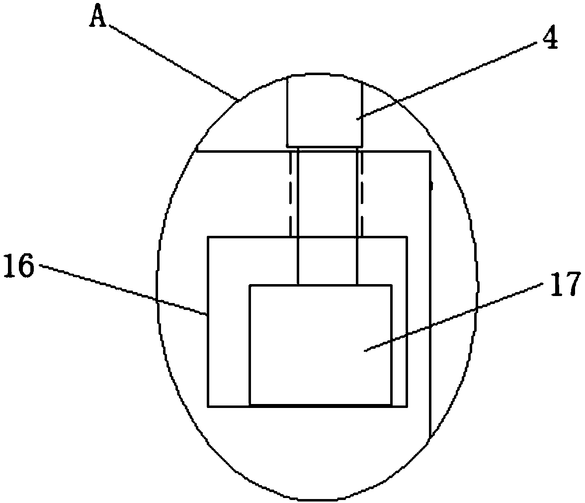
[0025] refer to Figure 1-5, a magnetic winding wire machine with positioning function, including a mounting plate 1, a sliding groove 2 is provided on one side of the mounting plate 1, a screw rod 4 is movably installed in the sliding groove 2, and a screw rod 4 is movably socketed on the screw rod 4 Two sliding blocks 3, and the two sliding blocks 3 are all slidably installed in the sliding groove 2, the sliding block 3 is provided with a threaded hole 5, the screw rod 4 is threadedly connected with the threaded hole 5, and there is an opening below the sliding groove 2. In the first cavity 16 on the mounting plate 1, the first rotating motor 17 ...


PUM


Abstract

The invention discloses a magnetic ring winding machine having a positioning function. The magnetic ring winding machine comprises an installation plate, wherein a sliding groove is formed in one sideof the installation plate, a screw rod is movably arranged in the sliding grove, two sliding blocks movably sleeve the screw rod, the two sliding blocks are arranged in the sliding groove in a sliding way, threaded holes are formed in the sliding blocks, the screw rod is in threaded connection with the threaded holes, a first cavity is formed in a position below the sliding groove and is formed in the installation plate, a first rotation motor is fixedly arranged on an inner wall of a bottom side of the first cavity, and an output shaft of the first rotation motor extends to the sliding groove and is fixedly arranged on a bottom end of the screw rod. By the magnetic ring winding machine, the positions of a fixed block and a support plate can be convenient to adjust, the tightness of a winding line is convenient to adjust, a magnetic ring winding wheel can be conveniently and stably fixed, meanwhile, the magnetic winding wheel during winding can be conveniently positioned, winding in mess is prevented, and excessive winding of the magnetic ring winding wheel can be prevented.

Description

technical field [0001] The invention relates to the technical field of winding machines, in particular to a magnetic winding machine with a positioning function. Background technique [0002] At present, many electronic products need a magnetic ring wound with enameled wire as an accessory. Due to the small size of the magnetic ring, its aperture is also small. In the existing technology, the winding is generally done manually, and the efficiency is very low. Due to the unevenness of the racket wire, the yield rate is not high, and the wound enameled wire is easily damaged. [0003] The patent with the application number 201310024882.0 discloses the winding mechanism of the magnetic winding wire machine. The mechanism includes a cylindrical cam fixed on the base and a crochet hook telescopically arranged on the base. A winding needle is driven by a turbine along the cylindrical cam The outer contour of the rotation to stir up or loosen the enameled wire; the surrounding nee...

Claims


Application Information

Patent Timeline
IPC IPC(8): H01F41/08H01F41/094H01F41/066
CPCH01F41/066H01F41/08H01F41/094
Inventor 沈国良沈海斌
Owner 惠州市瑞恺电子有限公司
Why Eureka
Try Eureka