
Multi-beam positioning method, device and system

A positioning device and positioning method technology, applied in the direction of location information-based services, electrical components, wireless communication, etc., can solve the problem of inaccurate distance values, achieve the effect of improving regional positioning accuracy and simple implementation methods

Active Publication Date: 2018-04-20
ELECTRIC POWER RES INST STATE GRID JIBEI ELECTRIC POWER COMPANY +3
View PDF5 Cites 1 Cited by
  • Summary
  • Abstract
  • Description
  • Claims
  • Application Information

AI Technical Summary

Problems solved by technology

[0014] In order to solve the problem that the distance value obtained by distance calculation based on large-scale fading is not accurate enough, the present invention proposes a multi-beam positioning method, device and system

Method used


Image

  • Multi-beam positioning method, device and system
  • Multi-beam positioning method, device and system
  • Multi-beam positioning method, device and system

Examples


Embodiment Construction

[0035] The following will clearly and completely describe the technical solutions in the embodiments of the present invention with reference to the accompanying drawings in the embodiments of the present invention. Obviously, the described embodiments are only some, not all, embodiments of the present invention. Based on the embodiments of the present invention, all other embodiments obtained by those skilled in the art without creative efforts fall within the protection scope of the present invention.

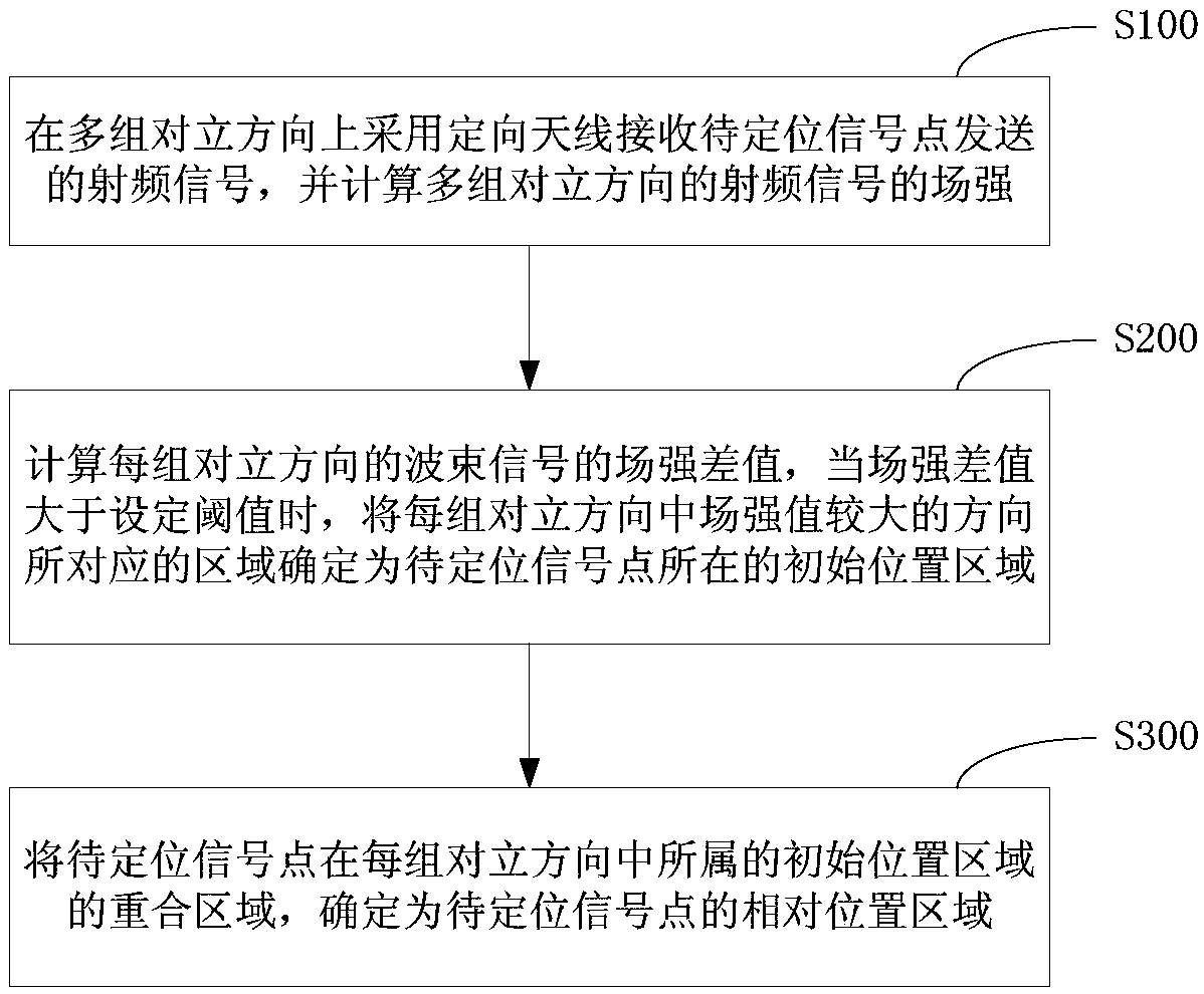
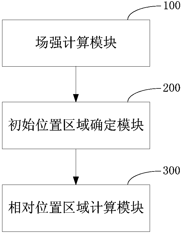
[0036] figure 2 It is a flowchart of a multi-beam positioning method according to an embodiment of the present invention, such as figure 2 As shown, the multi-beam positioning method includes: S100, using a directional antenna to receive the beam signals sent by the signal point to be positioned in multiple groups of opposing directions, and calculating the field strength of the beam signals in multiple groups of opposing directions; S200, calculating the The field strength...


PUM


Abstract

The invention provides a multi-beam positioning method, device and system, wherein the multi-beam positioning method comprises the steps of: receiving beam signals sent by a signal point to be positioned by using a directional antenna in multiple sets of alternative directions, and calculating the field strength of the beam signals in the multiple sets of alternative directions; calculating the field strength difference value of the beam signals in each set of alternative directions, and, when the field strength difference value is greater than a set threshold value, determining an area corresponding to the direction having a relatively high field strength value in each set of alternative directions as the initial position area, where the signal point to be positioned is; and, determiningthe overlap area of the signal point to be positioned in the initial position area in each set of alternative directions as the relative position area of the signal point to be positioned.

Description

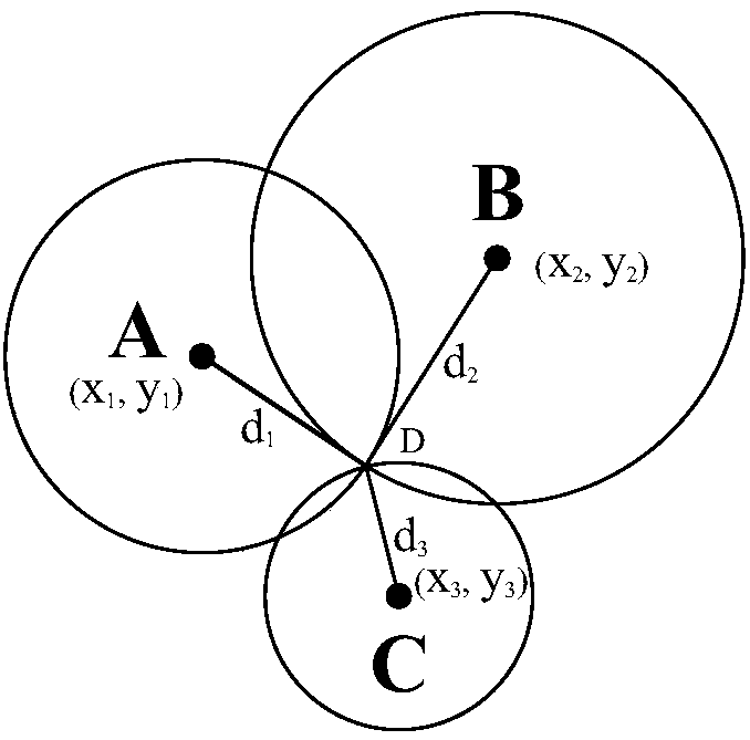
technical field [0001] The invention relates to the field of signal positioning, in particular to a multi-beam positioning method, device and system. Background technique [0002] RSSI (Received Signal Strength Indication) refers to the received signal strength indication, a positioning technology that measures the distance between the signal point and the receiving point through the strength of the received signal, and then performs positioning calculations based on the corresponding data [0003] At present, according to the received RSSI value, the distance between the signal receiving end and the signal transmitting end is usually calculated by the following traditional method, that is, the distance is fitted by using the large-scale fading of the signal in space, from the theoretical and practical In terms of measurement, if a free space model is used, the average received signal power RSSI value decreases logarithmically as the distance increases. [0004] The free sp...

Claims


Application Information

Patent Timeline
Patent Type & Authority Applications(China)
IPC IPC(8): H04W4/02H04W64/00
CPCH04W4/02H04W64/00
Inventor 姜振宇袁瑞铭鲁观娜王晨钟侃高舜安易忠林丁恒春徐占河刘影李文文吕言国赵林周丽霞王婷巨汉基李亮樊明延
Owner ELECTRIC POWER RES INST STATE GRID JIBEI ELECTRIC POWER COMPANY
Learn More