
Electronic equipment box

A technology for electronic equipment and enclosures, applied in the field of electronic equipment protection, can solve the problems of poor dustproof and waterproof effect, etc.

Inactive Publication Date: 2018-04-20
SHENZHEN KEHUA HENGSHENG TECH +1
View PDF13 Cites 1 Cited by
  • Summary
  • Abstract
  • Description
  • Claims
  • Application Information

AI Technical Summary

Problems solved by technology

[0004] In view of this, the object of the present invention is to provide an electronic equipment box, which can effectively solve the problem of poor dustproof and waterproof effects of the electronic equipment box

Method used


Image

  • Electronic equipment box
  • Electronic equipment box
  • Electronic equipment box

Examples


Embodiment Construction

[0024] The embodiment of the invention discloses an electronic equipment box to effectively solve the problem of poor dustproof and waterproof effects of the electronic equipment box.

[0025] The following will clearly and completely describe the technical solutions in the embodiments of the present invention with reference to the accompanying drawings in the embodiments of the present invention. Obviously, the described embodiments are only some, not all, embodiments of the present invention. Based on the embodiments of the present invention, all other embodiments obtained by persons of ordinary skill in the art without making creative efforts belong to the protection scope of the present invention.

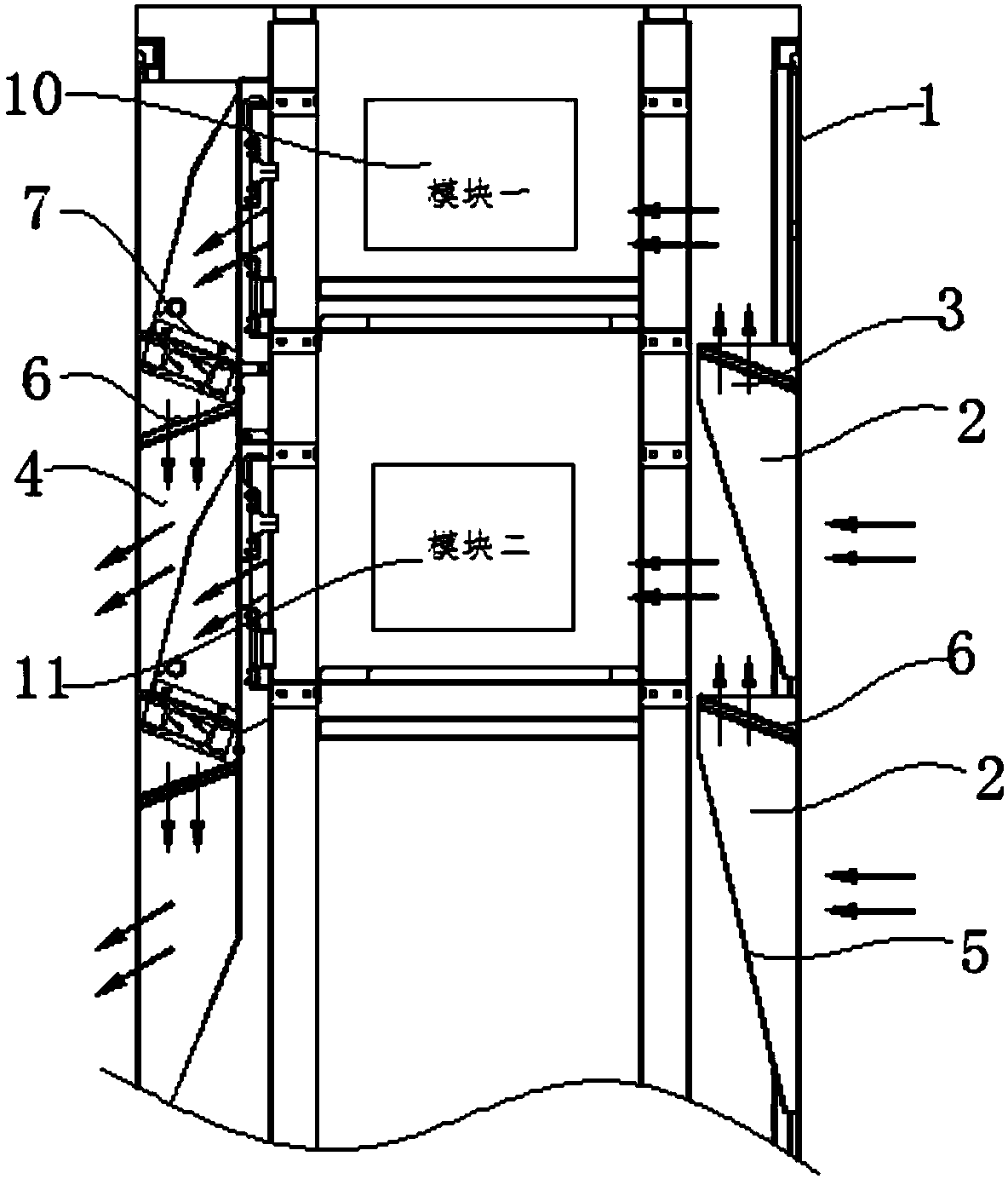
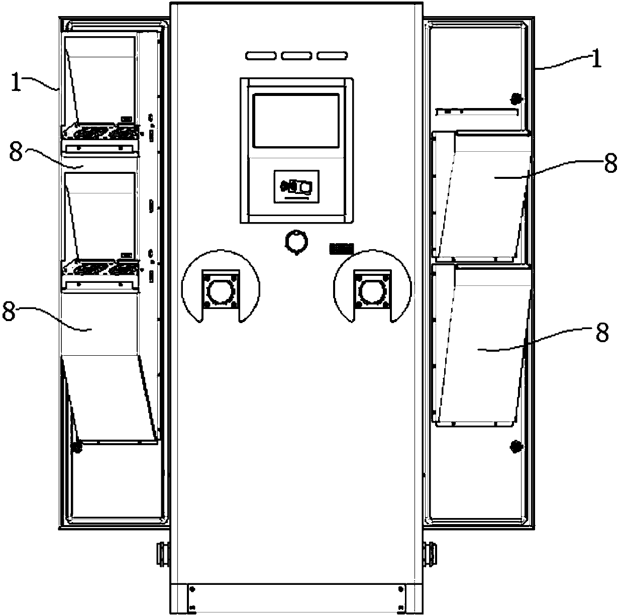
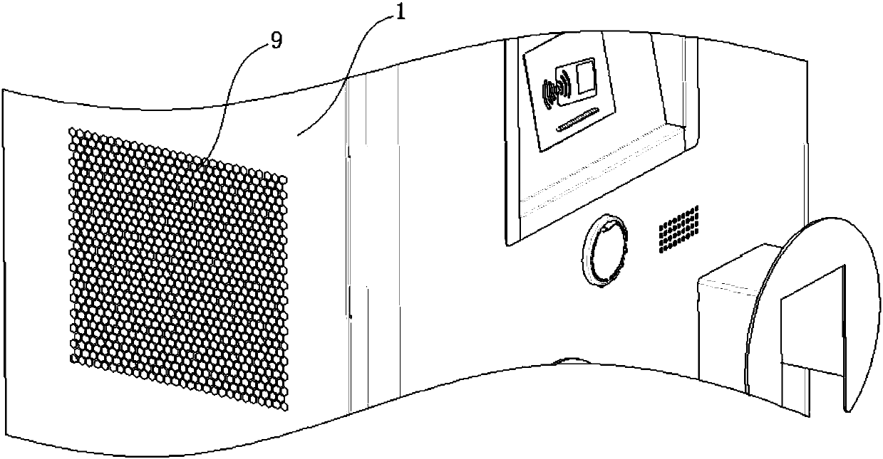
[0026] see Figure 1-Figure 3 , figure 1 A cross-sectional schematic diagram of an electronic equipment box provided by an embodiment of the present invention; figure 2 Schematic diagram of the configuration of the electronic equipment box in the unfolded state on both sides...


PUM

PropertyMeasurementUnit
heightaaaaaaaaaa
heightaaaaaaaaaa

Abstract

The invention discloses an electronic equipment box. The electronic equipment box comprises a box shell provided with a box cavity and a gas inlet passage for guiding external gas into the interior ofthe box cavity, wherein the gas inlet passage comprises a gravity separation section extending upwards vertically so as to carry out gravity separation on liquid and solid inside the gas. Inside theelectronic equipment box, the gravity separation section is arranged inside the gas inlet passage, the characteristic that the liquid and solid inside the gas are relatively large in density relativeto the gas is used in the gravity separation section, the liquid and solid inside the gas can be gradually slowed down and fall off through the gravity effect, and then external liquid and solid are effectively prevented from entering the box cavity. Above all, the electronic equipment box can effectively solve the problem that an existing electronic equipment box is low in dustproof and waterproof effects.

Description

technical field [0001] The invention relates to the technical field of electronic equipment protection, and more specifically relates to an electronic equipment box. Background technique [0002] At present, the heat dissipation of some charging pile integrated machines usually uses louvers for heat dissipation. Although the louvers can effectively prevent water from flowing into the inside, considering the outside air, there will be some water droplets floating in the air in rainy days, and then It is easy to flow with the air and enter the interior through the ventilation channel. In windy and sandy days, there are generally solid particles suspended in the outside air, floating in the air, and then easily flow with the air, and enter the interior through the ventilation channel. [0003] To sum up, how to effectively solve the problem of poor dustproof and waterproof effects of electronic equipment boxes is an urgent problem for those skilled in the art. Contents of th...

Claims


Application Information

Patent Timeline
Patent Type & Authority Applications(China)
IPC IPC(8): H05K5/02H05K7/20B01D50/00
CPCH05K5/0213H05K7/20145H05K7/20181B01D50/20
Inventor 王斌梁舒展甘绍朋兰祥金
Owner SHENZHEN KEHUA HENGSHENG TECH
Learn More