
Dust suppression device used in construction site

A dust suppression device and on-site technology, applied to the separation of dispersed particles, chemical instruments and methods, and the use of liquid separation agents, etc., can solve the problems of air pollution, single atomization dust reduction, poor dust reduction effect, etc., achieve high dust reduction efficiency and increase dust reduction Good range and dust reduction effect

Inactive Publication Date: 2018-04-24
张宁 +3
View PDF3 Cites 13 Cited by
  • Summary
  • Abstract
  • Description
  • Claims
  • Application Information

AI Technical Summary

Problems solved by technology

[0002] With the rapid development of social economy, social engineering construction is also changing with each passing day. At present, air pollution is often generated during the construction of the project site, which makes the content of large particles of dust in the air too high. In order to avoid affecting the surrounding environment and protect the safety of employees If you are healthy, you need to use various means to control the large particles of dust in the air. For the treatment of large particles of dust, spray dust reduction measures are usually used. The ordinary dust suppression device is a single atomization dust reduction, and the dust reduction effect is poor. Only precipitation is used. The way of dust removal, the dust removal effect is not ideal

Method used


Image

  • Dust suppression device used in construction site
  • Dust suppression device used in construction site
  • Dust suppression device used in construction site

Examples


Embodiment Construction

[0019] The following will clearly and completely describe the technical solutions in the embodiments of the present invention with reference to the accompanying drawings in the embodiments of the present invention. Obviously, the described embodiments are only some, not all, embodiments of the present invention. Based on the embodiments of the present invention, all other embodiments obtained by persons of ordinary skill in the art without making creative efforts belong to the protection scope of the present invention.

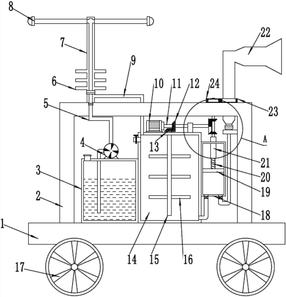
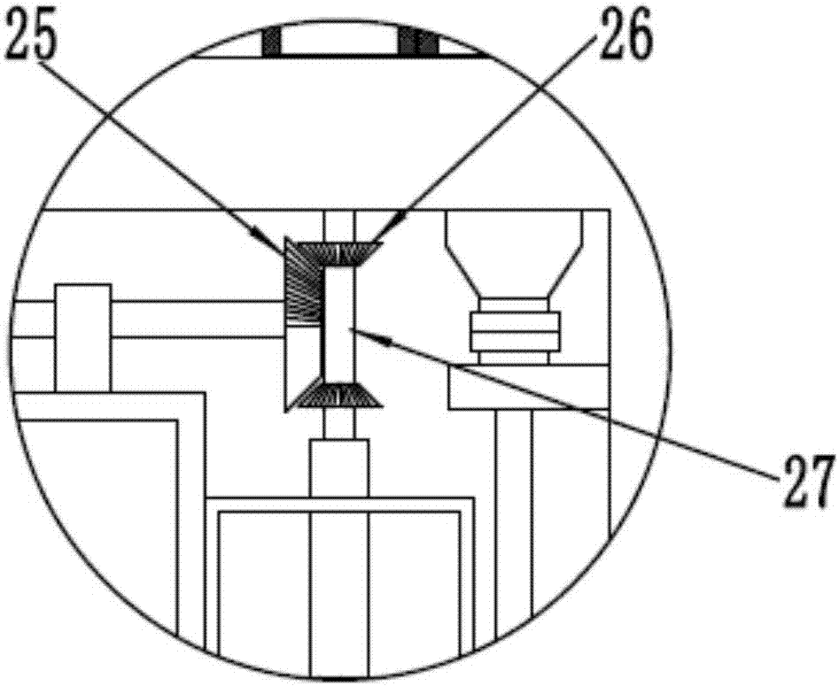
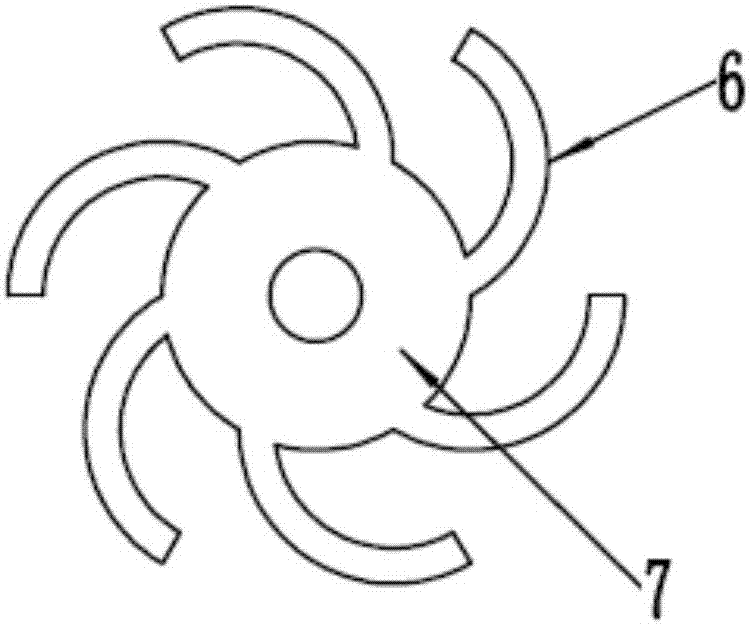
[0020] see Figure 1~3 , a dust suppression device on the engineering site, comprising a base plate 1, a casing 2, a water tank 3, an atomizing nozzle 8, a dust suction chamber 14 and a cylinder block 18; the lower end of the base plate 1 is symmetrically equipped with wheels 17, and the wheels 17 are arranged for It is convenient for the device to move; the housing 2 is fixedly installed on the upper end of the base plate 1, and the inner side of the housing ...


PUM


Abstract

The invention discloses a dust suppression device used in the construction site. The dust suppression device comprises a bottom plate, a casing, a water tank, an atomizing spray pipe, a dust suction cavity and a cylinder, wherein the casing is fixedly mounted at the upper end of the bottom plate, the dust suction cavity is formed in the inner side of the casing, a motor is arranged at the upper end of the dust suction cavity, and the output end of the motor is fixedly connected with a rotating shaft; the cylinder is fixedly mounted at the right end of the dust suction cavity, a piston is glidingly connected into the cylinder, the upper end of the piston is fixedly connected with a threaded rod, and the other end of the threaded rod is connected into a threaded sleeve in a threaded manner;the water tank is arranged on the left side of the dust suction cavity, the lower end of the water tank is fixedly connected with the bottom plate, and a water suction pump is arranged at the upper end of the water tank. According to the dust suppression device, dust suppression treatment is carried out in two modes simultaneously, so that dust suppression efficiency is high, and dust suppressioneffect is good; treated gas is introduced into a hollow cavity of a first rotating rod, the first rotating rod is driven to rotate under the action of arc-shaped spray pipes, therefore, the dust suppression range is enlarged, and energy is sufficiently utilized.

Description

technical field [0001] The invention relates to a dust suppression device, in particular to a dust suppression device on an engineering site. Background technique [0002] With the rapid development of social economy, social engineering construction is also changing with each passing day. At present, air pollution is often generated during the construction of the project site, which makes the content of large particles of dust in the air too high. In order to avoid affecting the surrounding environment and protect the safety of employees If you are healthy, you need to use various means to control the large particles of dust in the air. For the treatment of large particles of dust, spray dust reduction measures are usually used. The ordinary dust suppression device is a single atomization dust reduction, and the dust reduction effect is poor. Only precipitation is used. The way of dust removal, the dust removal effect is not ideal. Contents of the invention [0003] The o...

Claims


Application Information

Patent Timeline
Patent Type & Authority Applications(China)
IPC IPC(8): B01D47/02B01D47/08
Inventor 张宁刘志方徐红刘洁晶
Owner 张宁
Learn More