Glass gluing equipment capable of improving use stability

A kind of stability, glass technology, applied in the device, coating and other directions of coating liquid on the surface, can solve the problems of low gluing efficiency, inconvenient use, gluing on the glass frame, etc., to improve the gluing efficiency, improve the Stable, easy-to-use effects

Pending Publication Date: 2018-04-24
胡振宇
View PDF1 Cites 7 Cited by
  • Summary
  • Abstract
  • Description
  • Claims
  • Application Information

AI Technical Summary

Problems solved by technology

[0002] Glass is formed by melting silicon dioxide and other chemical substances. Its main component is silicate double salt, which is an amorphous solid with an irregular structure. It is widely used in buildings. There is usually a glass frame on the outside, but there is a gap between the glass frame and the glass, which is not conducive to the stability and fixation between the glass frame and the glass. Therefore, a glass gluing equipment that can improve the stability of use is needed. There is a positioning ring, the positioning ring is fixed with the support bar, there is an arc support bar between the support bars, the support plate and the support bar are fixed, there is a mounting plate between the support bars, the mounting plate is fixed with the support bar, and the mounting plate is concavely formed Groove, there is a baffle in the groove. For example, the patent application publication number 201520024678.3 discloses a glass gluing equipment that can improve the stability of use, but the above patents cannot improve the stability of the glass gluing equipment during use. , cannot be applied to the glue application of glass frames of different sizes, the glue application efficiency is not high, and it is inconvenient to use

Method used


Image

  • Glass gluing equipment capable of improving use stability
  • Glass gluing equipment capable of improving use stability
  • Glass gluing equipment capable of improving use stability

Examples


Embodiment Construction

[0020] The following will clearly and completely describe the technical solutions in the embodiments of the present invention with reference to the accompanying drawings in the embodiments of the present invention. Obviously, the described embodiments are only some, not all, embodiments of the present invention. Based on the embodiments of the present invention, all other embodiments obtained by persons of ordinary skill in the art without making creative efforts belong to the protection scope of the present invention.

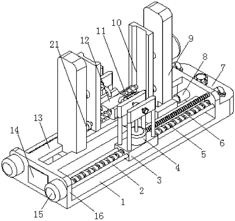
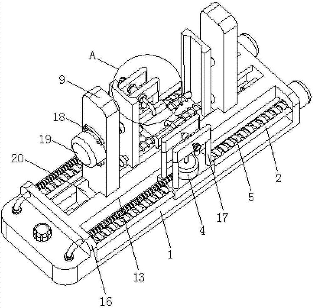
[0021] see Figure 1-3 , the present invention provides a technical solution: a glass gluing equipment that can improve the stability of use, including a base 1, a slide rail 13 is provided at the middle position on the upper side of the base 1, and two symmetrically distributed two sides of the base 1 are provided. Set of fixed plates 16, the side of the fixed plate 16 close to the slide rail 13 is connected with two groups of lead screws 5 symmetrically dist...


PUM


Abstract

The invention discloses a glass gluing equipment that can improve the stability of use. It includes a base. A slide rail is provided at the middle position of the upper side of the base. Two sets of symmetrically distributed fixed plates are provided on both sides of the base. There are two sets of sliding rods on the side of the fixed plate close to the screw, and a first sliding platform is provided in the middle of the sliding rod and the screw. One set of fixed plates is provided with a liquid storage tank on the side away from the slide rail. The side of the fixed plate close to the PLC controller is provided with two sets of symmetrically distributed first servo motors. The output shaft of the first servo motor is connected to one end of the rotating shaft through a coupling, and is connected through the side clamping plate and the bottom clamping plate. Used together, the stability of the glass gluing equipment can be improved. The output shaft of the second servo motor rotates to drive the side splints to rotate, thereby improving the gluing efficiency. The sliding shafts and springs provided between the side splints can be used for glass frames of different sizes. Gluing makes it easy to use.

Description

Technical field [0001] The present invention relates to the technical field of glass gluing equipment, specifically a glass gluing equipment that can improve the stability of use. Background technique [0002] Glass is formed by melting silica and other chemicals together. Its main component is silicate double salt. It is an amorphous solid with an irregular structure and is widely used in buildings. During installation, the glass is There is usually a glass frame on the outside, but there is a gap between the glass frame and the glass, which is not conducive to the stability and fixation between the glass frame and the glass. Therefore, a glass gluing equipment that can improve the stability of use is needed. The support bars are set between There is a positioning ring, the positioning ring is fixed to the support bar, an arc-shaped support bar is provided between the support bars, the support plate is fixed to the support bar, a mounting plate is provided between the suppo...

Claims


Application Information

Patent Timeline
Patent Type & Authority Applications(China)
IPC IPC(8): B05C5/02B05C11/10B05C13/02
CPCB05C5/0204B05C5/027B05C11/1002B05C13/02
Inventor 胡振宇
Owner 胡振宇
Why Eureka
Try Eureka