Staggered type magnetic fluid sealing device

A magnetic fluid sealing and staggered technology, which is applied in the direction of engine sealing, engine components, mechanical equipment, etc., can solve problems such as difficult to achieve vacuum sealing, inconspicuous effect, and failure to reach high speed, etc., to improve pressure resistance and sealing performance, expanding the safe working range, increasing the effect of magnetic field strength

Active Publication Date: 2018-04-24
GUANGXI UNIVERSITY OF TECHNOLOGY
View PDF6 Cites 9 Cited by
  • Summary
  • Abstract
  • Description
  • Claims
  • Application Information

AI Technical Summary

Problems solved by technology

[0005] 1. On the outer surface of the rotating shaft, the area where the magnetic fluid is sealed is the optical axis section. Once the magnetic fluid leaks, it will cause a complete leak and the seal will fail
[0006] 2. If a single-stage seal is used, the magnetic supply capacity is weak, the magnetic sealing performance is poor, and it is difficult to meet the requirements of vacuum sealing; if a multi-stage seal is used, the sealing performance can be improved, but the effect is not obvious, and it cannot reach high speed, etc. The needs of the occasion, the scope of application is narrow
Moreover, the use of multi-stage sealing will make the equipment size large and occupy space

Method used


Image

  • Staggered type magnetic fluid sealing device

Examples


Embodiment Construction

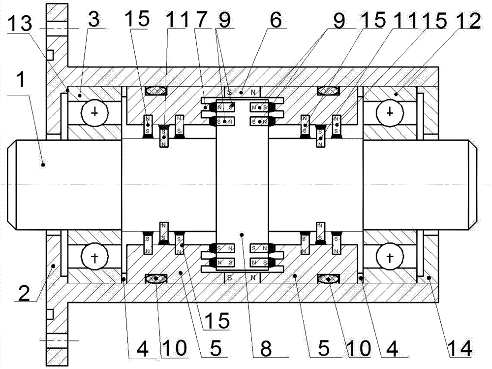
[0034] Such as figure 1 As shown, a staggered magnetic fluid sealing device includes a hollow housing 2, a rotating shaft 1 arranged in the inner cavity of the housing 2, and a radial direction between the outer surface of the rotating shaft 1 and the inner wall of the housing 2 is provided. The axially magnetized first permanent magnet 6 is provided with pole shoes 5 on both sides of the first permanent magnet 6 .

[0035] At least one third groove is formed in the upper direction of the rotating shaft 1 , and a third permanent magnet 11 is arranged in each third groove.

[0036] At least one fourth groove is provided on the inner surface of each pole piece 5 in the circumferential direction, and a fourth permanent magnet 15 is arranged in each fourth groove.

[0037] The third permanent magnet 11 and the fourth permanent magnet 15 are radially magnetized split permanent magnet rings with opposite polarities.

[0038] The outer circular surface of the third permanent magnet...


PUM


Abstract

The invention discloses a staggered type magnetic fluid sealing device. The magnetic fluid sealing device comprises a hollow shell, a rotating shaft and first permanent magnets; pole shoes are arranged on the two sides of each first permanent magnet, at least one third groove is formed in the rotating shaft in the circumferential direction, and third permanent magnets are arranged in the third grooves respectively; at least one fourth groove is formed in the inner circular surface of each pole shoe in the circumferential direction, and fourth permanent magnets are arranged in the fourth grooves respectively; the third permanent magnets and the fourth permanent magnets are radially magnetized permanent magnet rings, and the polarities of the third permanent magnets and the fourth permanentmagnets are opposite; third gaps exist between the outer circular surfaces of the third permanent magnets and the inner circular surfaces of the pole shoes; fourth gaps exist between the inner circular surfaces of the fourth permanent magnets and the outer surface of the rotating shaft; the third permanent magnets and the fourth permanent magnets are distributed alternately in the axial directionin a staggered mode; and magnetic fluids are injected into the third gaps and the fourth gaps. According to the magnetic fluid sealing device, structure is improved, so that the intensity of a magnetic field in the gaps is increased, and the pressure resistance and the sealing performance of the magnetic fluid seal are improved.

Description

technical field [0001] The invention belongs to the sealing technology, and in particular relates to a staggered magnetic fluid sealing device. Background technique [0002] The magnetic fluid seal has the advantages of no solid friction between the seals, long service life of the seals, and zero leakage. [0003] The existing magnetic fluid sealing structure generally includes a housing with a hollow cavity, a rotating shaft, a permanent magnet and a pole shoe are arranged between the rotating shaft and the housing for magnetic fluid sealing, and the inner ring of the pole shoe is provided with pole teeth. [0004] This structure mainly has the following defects: [0005] 1. On the outer surface of the rotating shaft, the area where the magnetic fluid is sealed is the optical axis section. Once the magnetic fluid leaks, it will cause complete leakage and the seal will fail. [0006] 2. If a single-stage seal is used, the magnetic supply capacity is weak, the magnetic seal...

Claims


Application Information

Patent Timeline
Patent Type & Authority Applications(China)
IPC IPC(8): F16J15/43
CPCF16J15/43
Inventor 杨小龙郝付祥陈帆孙彭何美丽谢国进
Owner GUANGXI UNIVERSITY OF TECHNOLOGY
Why Eureka
Try Eureka