A conical magnetic fluid sealing device

A magnetic fluid sealing and conical technology, applied in the direction of engine sealing, bearing components, engine components, etc., can solve the problems of limiting the application of magnetic fluid sealing technology, unfavorable sealing performance stability, and magnetic fluid sealing performance reduction, etc. The performance reliability is poor, the withstand voltage capability is improved, and the magnetic source is sufficient.

Active Publication Date: 2018-03-20
GUANGXI UNIVERSITY OF TECHNOLOGY
View PDF6 Cites 2 Cited by
  • Summary
  • Abstract
  • Description
  • Claims
  • Application Information

AI Technical Summary

Problems solved by technology

When the magnetic fluid sealing technology is applied in a large-diameter, high-speed and heavy-duty sealing environment, the large radial runout of the rotating shaft requires a large sealing gap, and the performance of the magnetic fluid sealing decreases significantly with the increase of the sealing gap. It is conducive to the stability of sealing performance, thus limiting the application of magnetic fluid sealing technology in large gaps, high speed and heavy load conditions
Therefore, it is of great significance to improve the performance of magnetic fluid sealing under the condition of large gap. The existing magnetic fluid sealing device has the problem of low pressure resistance under the condition of large gap.

Method used


Image

  • A conical magnetic fluid sealing device

Examples


Embodiment Construction

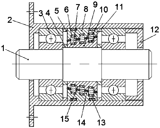
[0021] The present invention will be further described below in conjunction with the accompanying drawings.

[0022] Such as figure 1 The described conical magnetic fluid sealing device comprises an outer pole shoe 8, an inner pole shoe 9, an outer permanent magnet 10, and an inner permanent magnet 11. The inner pole shoe 9 is set on the shaft 1, and the inner pole shoe 9 The outer wall of the cone is a conical surface, and a plurality of annular grooves I7 are arranged at intervals on the conical surface, and the part between two adjacent annular grooves I7 is a pole tooth I15; the inner permanent magnet is installed in the annular groove I7 11;

[0023] The outer pole shoe 8 is installed on the inner wall of the housing 2, the inner wall of the outer pole shoe 8 is a conical surface, the inner wall of the outer pole shoe 8 and the outer wall of the inner pole shoe 9 are parallel to each other, and the inner wall of the outer pole shoe 8 corresponds to an annular recess. A ...


PUM


Abstract

The invention relates to the technical field of mechanical engineering sealing, and particularly relates to a cone magnetic fluid sealing device. The device comprises an outer pole piece, an inner pole piece, outer permanent magnets and inner permanent magnets, wherein the inner pole piece sleeves a shaft, the outer wall of the inner pole piece is a conical surface, a plurality of annular grooves I are formed in the conical surface at intervals, and pole teeth I are formed between two adjacent annular grooves I; the inner permanent magnets are installed in the annular grooves I; the outer pole piece is installed on the inner wall of a shell, the inner wall of the outer pole piece is a conical surface, the inner wall of the outer pole piece is parallel to the outer wall of the inner pole piece, a plurality of annular grooves II which correspond to the annular grooves I are formed in the inner wall of the outer pole piece, and pole teeth II are formed between two adjacent annular grooves II; the outer permanent magnets are respectively installed in the annular grooves II; the pole teeth I respectively correspond to the pole teeth II, and gaps are formed between the pole teeth I and the pole teeth II. The sealing device has high pressure-resistant capacity, and the problem of poor sealing performance and reliability of an existing large-gap magnetic fluid sealing device is solved.

Description

technical field [0001] The invention relates to the technical field of mechanical engineering sealing, in particular to a conical magnetic fluid sealing device. Background technique [0002] Magnetic fluid seals have the advantages of zero leakage and no rigid friction, and are widely used in various industries. However, the bearing pressure value of the magnetic fluid shaft seal is very sensitive to the size of the seal gap. If the seal gap increases by 0.1mm, the pressure bearing value of the magnetic fluid shaft seal can be reduced by more than 10%. When the magnetic fluid sealing technology is applied in a large-diameter, high-speed and heavy-duty sealing environment, the large radial runout of the rotating shaft requires a large sealing gap, and the performance of the magnetic fluid sealing decreases significantly with the increase of the sealing gap. It is conducive to the stability of sealing performance, thus limiting the application of magnetic fluid sealing techno...

Claims


Application Information

Patent Timeline
Patent Type & Authority Patents(China)
IPC IPC(8): F16C33/82F16J15/43
CPCF16C33/82F16J15/43
Inventor 杨小龙宾仕博谢国进何美丽
Owner GUANGXI UNIVERSITY OF TECHNOLOGY
Why Eureka
Try Eureka