Monitor connecting support moving mechanism

A technology for connecting brackets and moving mechanisms, which is applied in the direction of machines/supports, supporting machines, mechanical equipment, etc., can solve problems such as unsuitable for monitor adjustment, impossible monitoring, etc., to expand the monitoring angle of view, reduce restrictions, and have strong practicability Effect

Pending Publication Date:
View PDF7 Cites 11 Cited by
  • Summary
  • Abstract
  • Description
  • Claims
  • Application Information

AI Technical Summary

Problems solved by technology

[0002] With the continuous development of the field of image technology and in order to ensure people's personal safety more safely, monitoring equipment has developed very rapidly. Although the current monitoring equipment can meet the requirements of monitoring in most environments, most Part of the monitoring devices are fixed in the same place, even if it is a wide-angle camera, it is impossible to monitor the entire surrounding environment, so it has certain limitations in use
Although there is a mechanism that can realize the movement of the monitor, the movable mechanism in the prior art is a screw drive mechanism, that is, the screw drive mechanism is placed under the mobile slide table, and the slide table is controlled by the lead screw to move on the guide rail. , but there are many problems in this situation. For example, it can only run according to the set trajectory. As a result, there are limitations in the movement of the monitor. Mobile mechanism that can operate under different trajectories

Method used


Image

  • Monitor connecting support moving mechanism
  • Monitor connecting support moving mechanism
  • Monitor connecting support moving mechanism

Examples


Embodiment Construction

[0013] It should be noted that, in the case of no conflict, the embodiments of the present invention and the features in the embodiments can be combined with each other.

[0014] The present invention will be described in detail below with reference to the accompanying drawings and examples.

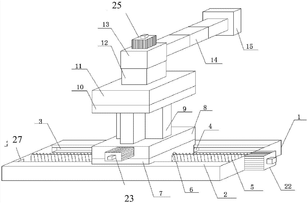
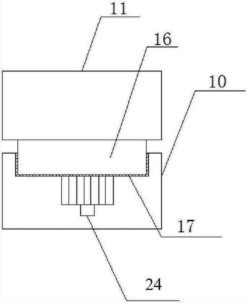
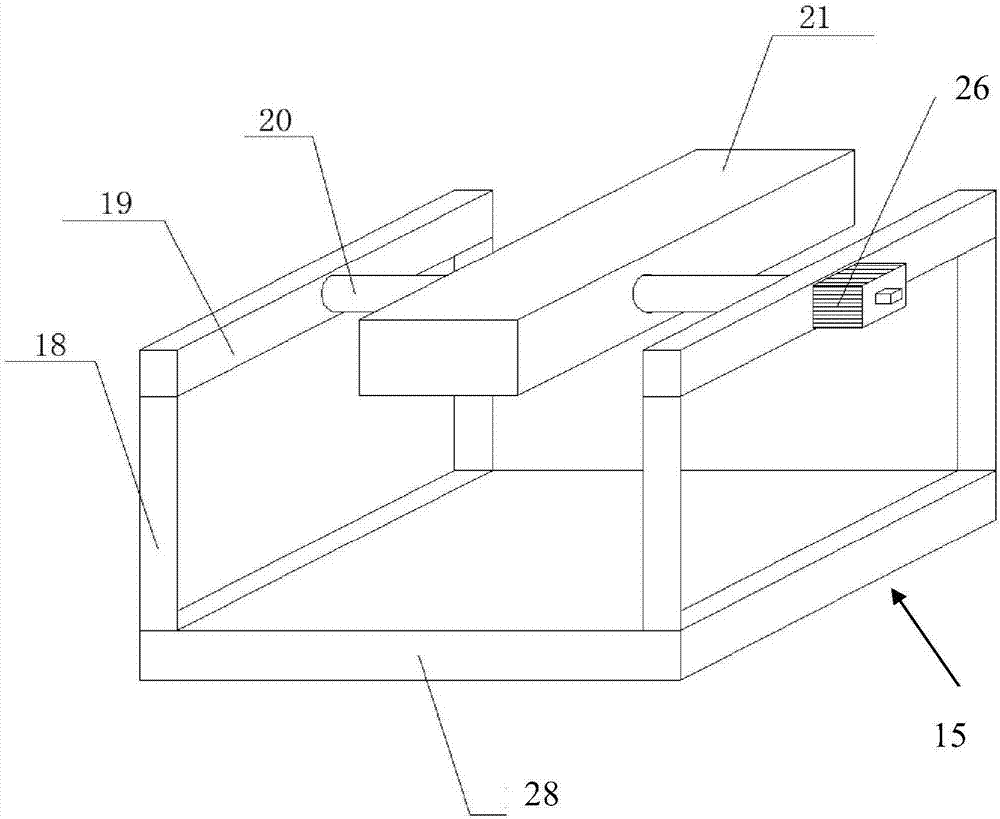
[0015] Such as figure 1 , figure 2 and image 3 As shown, the moving mechanism of the monitor connection bracket provided by the present invention includes a base 1, a lead screw 5, a first connecting platform 7, a first working platform 8, a telescopic column 9, a second connecting platform 10, a second working platform 11, a support Rod 12, third workbench 13, telescopic rod 14, bracket 15, first to fifth motors 23-26; wherein, the base 1 is a rectangular frame structure arranged horizontally, on the opposite sides of the two long sides 2 A chute 3 is respectively recessed along the length direction; the lead screw 5 is arranged inside the base 1 in a rotating manner, and is arrang...


PUM


Abstract

A monitor connecting support moving mechanism includes a base, a lead screw, a first connecting table, a first working table, a telescopic column, a second connecting table, a second working table, asupporting rod, a third working table, a telescopic rod, a support, a first motor, a second motor, a third motor, a fourth motor and a fifth motor. The monitor connecting support moving mechanism hasthe beneficial effects that the mechanism can be moved in three-dimensional space, the moving trajectory of the monitor is enlarged, the monitoring range of the monitor is enlarged at the same time, and the monitor can be freely rotated on the support to expand the monitoring viewing angle of the monitor to some extent; and the moving mechanism can complete running of the monitor through the leadscrew and the telescopic rod to enable the monitor to be more stable during running, the filmed quality of the monitor can be guaranteed, the limitation of the rail can be reduced when the monitor moves in three-dimensional space, and the monitor connecting support moving mechanism has the characteristics of simple structure, convenient using and powerful practicability.

Description

technical field [0001] The invention belongs to the technical field of connecting components, and in particular relates to a moving mechanism for a monitor connecting bracket. Background technique [0002] With the continuous development of the field of image technology and in order to ensure people's personal safety more safely, monitoring equipment has developed very rapidly. Although the current monitoring equipment can meet the requirements of monitoring in most environments, most Part of the monitoring devices are fixed in the same place. Even wide-angle cameras cannot monitor the entire surrounding environment, so there are certain limitations in use. Although there is a mechanism that can realize the movement of the monitor, the movable mechanism in the prior art is a screw drive mechanism, that is, the screw drive mechanism is placed under the mobile slide table, and the slide table is controlled by the lead screw to move on the guide rail. , but there are many prob...

Claims


Application Information

Patent Timeline
Patent Type & Authority Applications(China)
IPC IPC(8): F16M13/02F16M11/06F16M11/18H04N7/18
CPCH04N7/185F16M11/043F16M11/06F16M11/18F16M13/02
Inventor 王旭陈建李长河王梓赵德奇
Why Eureka
Try Eureka