A power battery insertion mechanism

A power battery and plug-in technology, applied in circuits, electrical components, circuit/collector parts, etc., can solve the problems of low efficiency, numerous sockets and laborious plug-in efficiency, etc., and achieve the effect of improving work efficiency

Active Publication Date: 2019-11-05
SHANGHAI JIAO TONG UNIV
View PDF6 Cites 0 Cited by
  • Summary
  • Abstract
  • Description
  • Claims
  • Application Information

AI Technical Summary

Problems solved by technology

At present, these wiring harnesses are all manually installed, and there are many and diverse sockets, and the insertion is laborious and inefficient.

Method used


Image

  • A power battery insertion mechanism
  • A power battery insertion mechanism
  • A power battery insertion mechanism

Examples


Embodiment 1

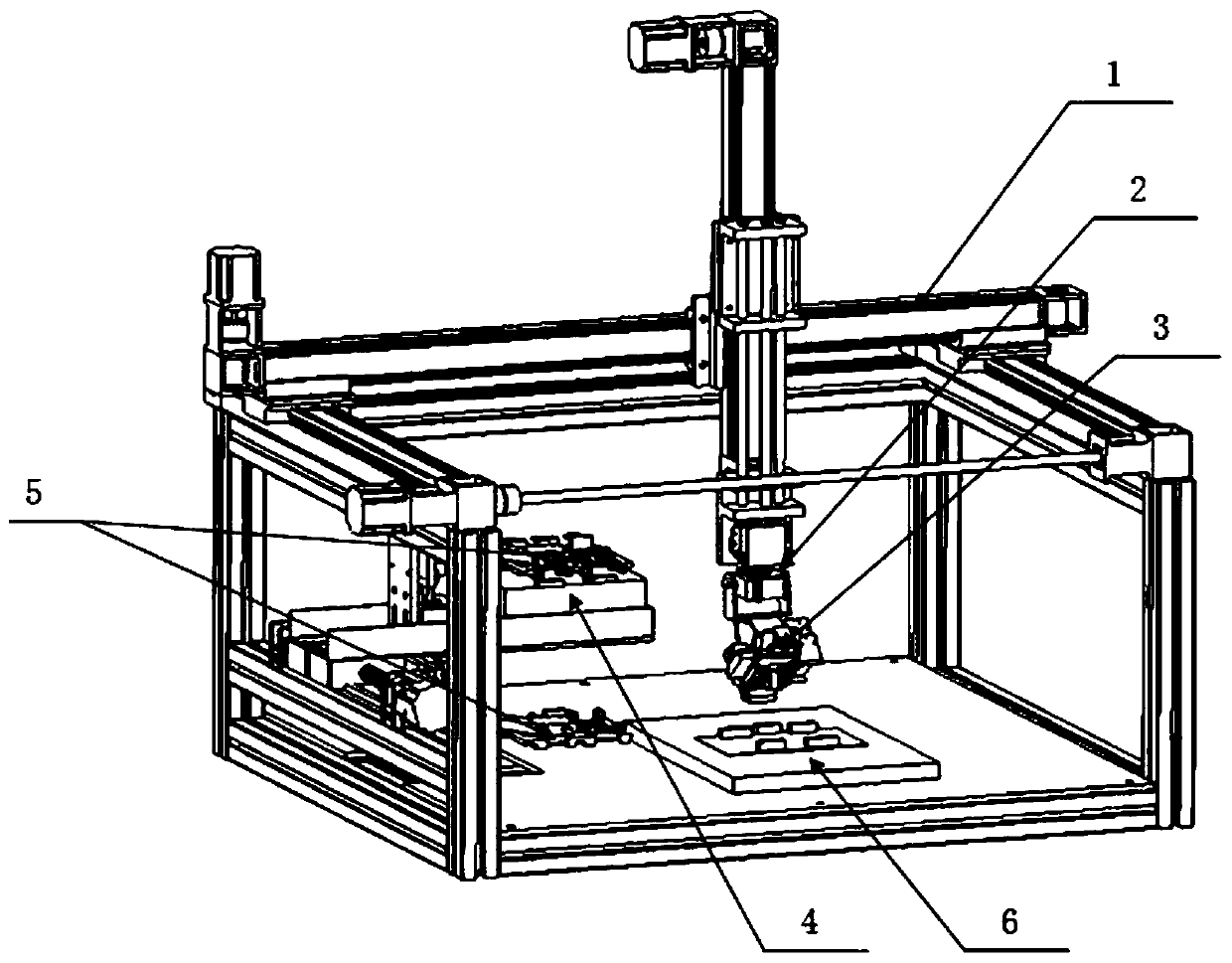
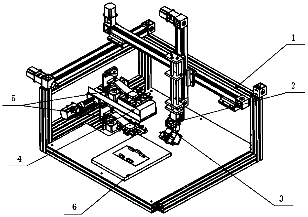
[0029] see figure 1 as well as figure 2 , a power battery wire insertion mechanism, including a control terminal (not shown in the figure), a mobile platform 1, and a wire-strapping device 3 installed on the mobile terminal 2 of the mobile platform 1 and electrically connected to the control terminal.

[0030] With the above structure, the control terminal controls the threading device 3 to pick up the wire harness, and performs threading operations on both ends of the wire harness to fix and clamp the plug of the wire harness; the threading device 3 is installed on the mobile terminal 2 of the mobile platform 1, and the control terminal controls The mobile terminal 2 and the thread-strapping device 3 are used to complete the plug-in operation with the socket of the power battery 4, and an automatic device is used instead of manpower to realize the plug-in of the wire harness, which improves work efficiency.

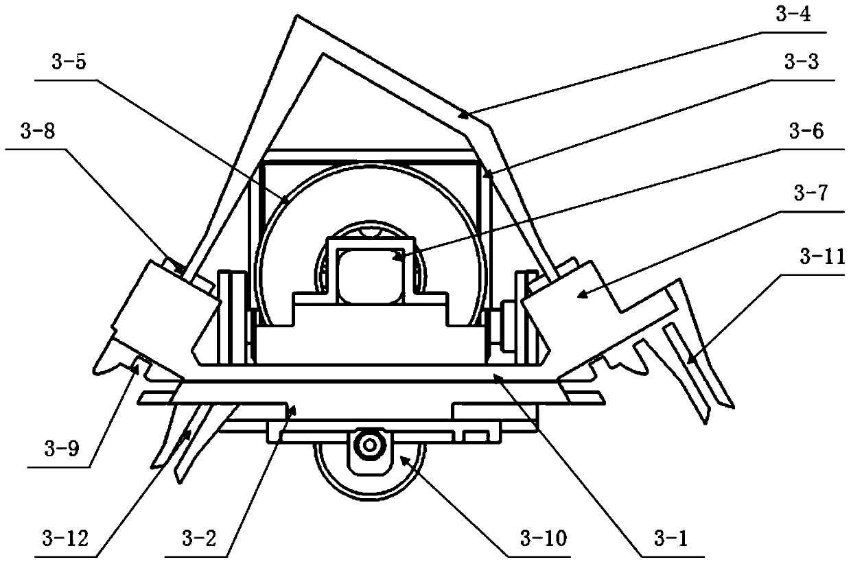
[0031] Further, see image 3 as well as Figure 4 , in a specif...

Embodiment 2

[0037] see Figure 5 , in order to ensure that the wiring harness plug and the battery jack can be aligned when the wiring harness is plugged in, to improve the accuracy of plugging, and to prevent damage to the plug and the jack due to position deviation during the plugging process, this embodiment is in the embodiment On the basis of 1, a further improvement is made. The power battery wire insertion mechanism in this embodiment also includes a positioning plate 5 for auxiliary wire insertion. The horizontal guide piece 5-1 corresponding to the horizontal insertion hole of the battery is also provided with a vertical guide groove 5-2 corresponding to the vertical insertion hole of the battery.

[0038] Further, the first end of the upper splint 3-1 is provided with a first guide groove 3-11, and the second end of the lower splint 3-2 is provided with a second guide groove 3-12; When inserting wires, the horizontal guide piece 5-1 snaps into the first guide groove 3-11 or the...


PUM


Abstract

The invention discloses a power battery wire plugging mechanism, which comprises a control terminal, a mobile platform, and a wire stroking device which is installed on a mobile end of the mobile platform and electrically connected with the control terminal. The power battery wire plugging mechanism provided by the invention can perform stroking operations at both ends after picking up a wire harness, and fixes and clamps a plug to complete the plugging operation with jacks.

Description

technical field [0001] The invention belongs to the field of power battery wire harness connection, and in particular relates to a power battery wire insertion mechanism with a wire pulling device. Background technique [0002] As the world's energy situation continues to be severe, new energy vehicles that do not use traditional fuels are increasingly being advocated and encouraged by everyone. Among them, electric vehicles have become the key direction of enterprise research and development, and with the development of technology, they have also realized commercial applications and gradually entered people's lives. [0003] One of the core components of an electric vehicle—the heart—is its power battery. In the power battery integration of electric vehicles, there are many wiring harnesses that need to be connected and installed. At present, these wiring harnesses are all manually installed, and there are many and varied sockets, and the insertion is laborious and ineffi...

Claims


Application Information

Patent Timeline
Patent Type & Authority Patents(China)
IPC IPC(8): H01R43/26H01R43/28
CPCH01R43/26H01R43/28H01R2201/26
Inventor 罗磊桑浩楠顾城歌刘亚雄
Owner SHANGHAI JIAO TONG UNIV
Why Eureka
Try Eureka