Adjustable water dispenser

A water dispenser and water bucket technology, which is applied in the field of adjustable water dispensers, can solve the problems of heavy burden, easy fall of the water bucket, and inability to adjust, etc., and achieve the effect of lightening the burden, not easy to fall, and simple structure

Active Publication Date: 2018-04-27
徐佳俊
View PDF5 Cites 6 Cited by
  • Summary
  • Abstract
  • Description
  • Claims
  • Application Information

AI Technical Summary

Problems solved by technology

[0005] The present invention overcomes that the existing water dispenser usually adopts a traditional structure, which cannot be adjusted. People need to move the heavy bucket to a high place before ins

Method used


Image

  • Adjustable water dispenser
  • Adjustable water dispenser
  • Adjustable water dispenser

Examples


Embodiment 1

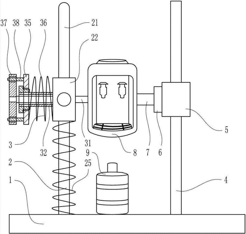
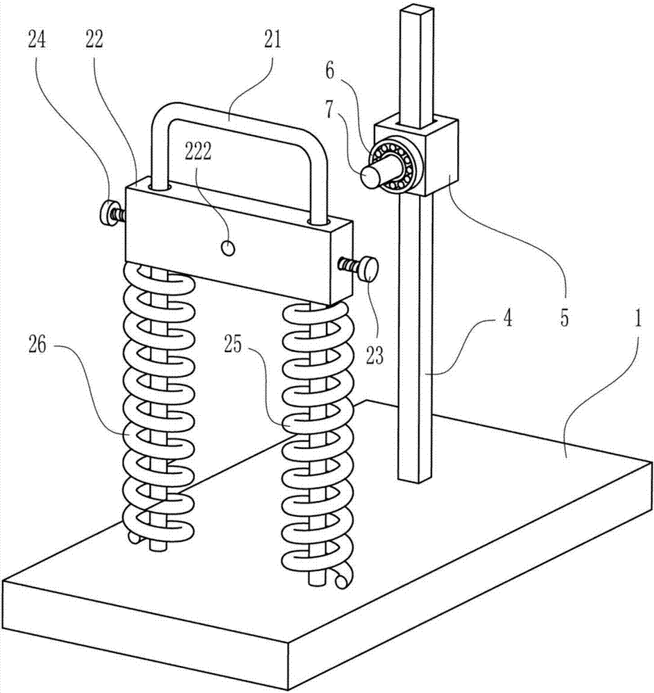
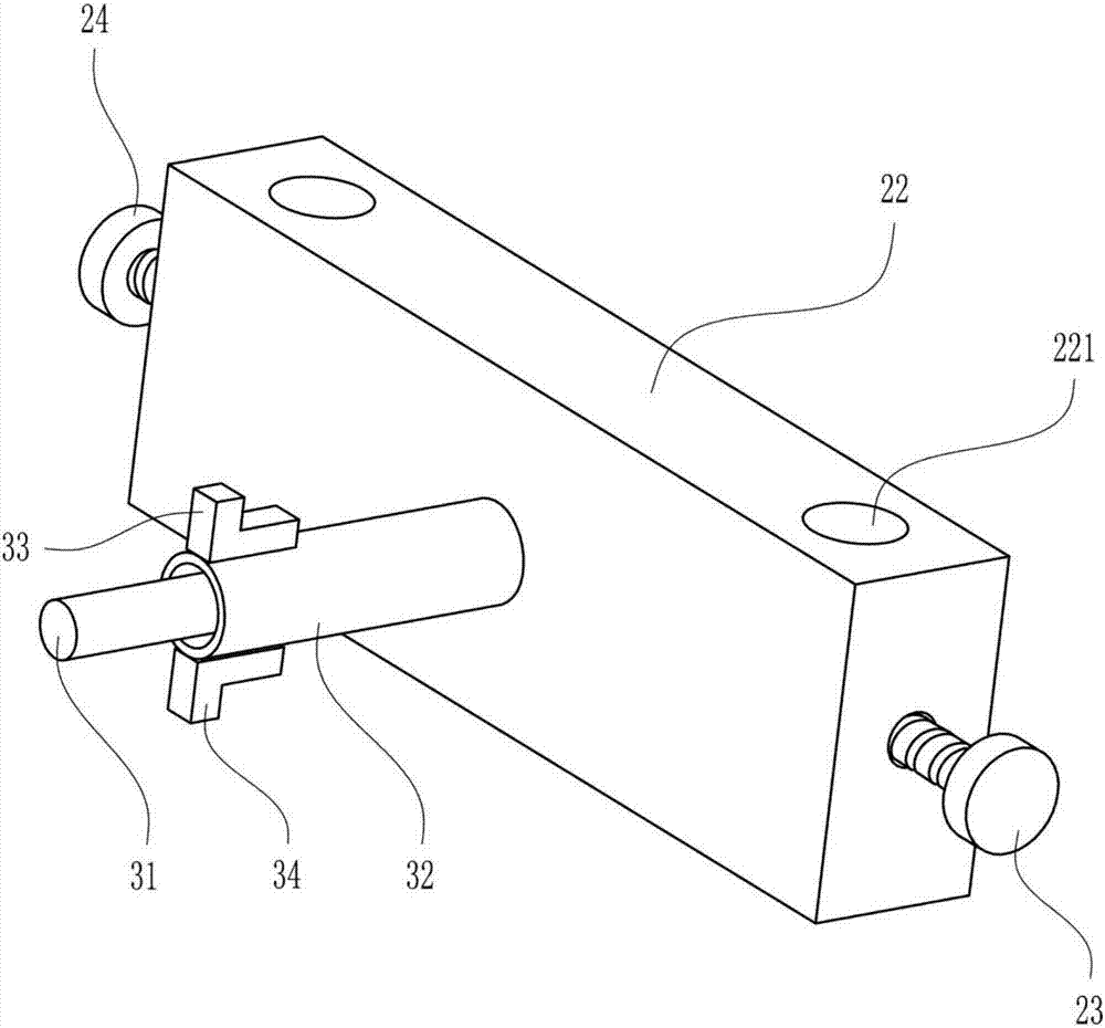
[0038] An adjustable water dispenser, such as Figure 1-12 As shown, it includes a first base 1, a lifting device 2, a rotating device 3, a rectangular guide rod 4, a rectangular guide sleeve 5, a bearing 6, a large rotating shaft 7, a water dispenser 8 and a bucket 9; Lifting device 2 and rotating device 3 are arranged, and lifting device 2 is connected with first base 1, and rotating device 3 is connected with lifting device 2, and rectangular guide rod 4 is positioned at the right side of rotating device 3, and the lower end of rectangular guide rod 4 is connected with the first base. The top of a base 1 is fixedly connected, and the rectangular guide sleeve 5 is slidably placed on the rectangular guide rod 4. The bearing 6 is located on the left side of the rectangular guide sleeve 5. The bearing 6 and the rectangular guide sleeve 5 are fixedly connected, and the large rotation The right end of the shaft 7 and the bearing 6 are set as an interference connection, the right ...

Embodiment 2

[0040] An adjustable water dispenser, such as Figure 1-12 As shown, it includes a first base 1, a lifting device 2, a rotating device 3, a rectangular guide rod 4, a rectangular guide sleeve 5, a bearing 6, a large rotating shaft 7, a water dispenser 8 and a bucket 9; Lifting device 2 and rotating device 3 are arranged, and lifting device 2 is connected with first base 1, and rotating device 3 is connected with lifting device 2, and rectangular guide rod 4 is positioned at the right side of rotating device 3, and the lower end of rectangular guide rod 4 is connected with the first base. The top of a base 1 is fixedly connected, and the rectangular guide sleeve 5 is slidably placed on the rectangular guide rod 4. The bearing 6 is located on the left side of the rectangular guide sleeve 5. The bearing 6 and the rectangular guide sleeve 5 are fixedly connected, and the large rotation The right end of the shaft 7 and the bearing 6 are set as an interference connection, the right ...

Embodiment 3

[0043] An adjustable water dispenser, such as Figure 1-12As shown, it includes a first base 1, a lifting device 2, a rotating device 3, a rectangular guide rod 4, a rectangular guide sleeve 5, a bearing 6, a large rotating shaft 7, a water dispenser 8 and a bucket 9; Lifting device 2 and rotating device 3 are arranged, and lifting device 2 is connected with first base 1, and rotating device 3 is connected with lifting device 2, and rectangular guide rod 4 is positioned at the right side of rotating device 3, and the lower end of rectangular guide rod 4 is connected with the first base. The top of a base 1 is fixedly connected, and the rectangular guide sleeve 5 is slidably placed on the rectangular guide rod 4. The bearing 6 is located on the left side of the rectangular guide sleeve 5. The bearing 6 and the rectangular guide sleeve 5 are fixedly connected, and the large rotation The right end of the shaft 7 and the bearing 6 are set as an interference connection, the right s...


PUM


Abstract

The invention relates to a water dispenser, and particularly aims at achieving the technical purpose of providing an adjustable water dispenser. In order to achieve the technical purpose, the adjustable water dispenser comprises a first base, a lifting device, a rotating device, a rectangular guide rod and the like; the lifting device is connected with the first base, the rotating device is connected with the lifting device, the rectangular guide rod is located at the right side of the rotating device, the lower end of the rectangular guide rod is fixedly connected with the top of the first base, a rectangular guide sleeve slidingly sleeves the rectangular guide rod, and a bearing is located at the left side of the rectangular guide sleeve and fixedly connected with the rectangular guide sleeve. The adjustable water dispenser is provided with the lifting device and the rotating device, the vertical position of the water dispenser can be conveniently adjusted through the lifting device,water remaining in the water dispenser can be conveniently discharged through the rotating device, and cleaning is conducted quickly and conveniently.

Description

technical field [0001] The invention relates to a water dispenser, in particular to an adjustable water dispenser. Background technique [0002] The water dispenser is a device that heats up or cools down the barreled pure water or mineral water and makes it convenient for people to drink. Put the bottled water above the machine and use it with the bottled water. Barrel water dispensers appeared before the middle of the 20th century. This type of water dispenser is designed as a special connector on the top of the fuselage to place the bucket upside down. The latest foreign water dispensers put the barreled water in the lower part of the machine. Water pump suction, this method is safer and more hygienic than conventional drinking fountains. Due to the difference of drinking fountains, there are many specifications of buckets. Among the many brands and models of water dispensers, water dispensers can be summed up in three types: warm, ice hot, and ice warm. Ice heat machine...

Claims


Application Information

Patent Timeline
IPC IPC(8): A47J31/44A47J31/00
CPCA47J31/002A47J31/44
Inventor 范中麟汪浩莫婉艺
Owner 徐佳俊
Why Eureka
Try Eureka