
Automatic drilling machine for flow collecting pipe

A technology for collecting pipes and drilling machines, which is applied in the direction of metal processing machinery parts, clamping, supporting, etc., can solve problems such as unstable positioning of pipe fittings, and achieve the effects of reducing costs, improving quality, and improving processing quality

Pending Publication Date: 2018-04-27
ZHONGSHAN OMS AUTOMATION EQUIP
View PDF0 Cites 10 Cited by
  • Summary
  • Abstract
  • Description
  • Claims
  • Application Information

AI Technical Summary

Problems solved by technology

[0003] In order to solve the problem of unstable positioning of pipe fittings welded at 90° in the prior art, the present invention provides an automatic header drilling machine with a relatively simple structure

Method used


Image

  • Automatic drilling machine for flow collecting pipe
  • Automatic drilling machine for flow collecting pipe
  • Automatic drilling machine for flow collecting pipe

Examples


Embodiment Construction

[0029] In order to make the technical problems, technical solutions and beneficial effects solved by the present invention clearer, the present invention will be further described in detail below in conjunction with the accompanying drawings and embodiments. It should be understood that the specific embodiments described here are only used to explain the present invention, not to limit the present invention.

[0030] The present invention is achieved through the following technical solutions:

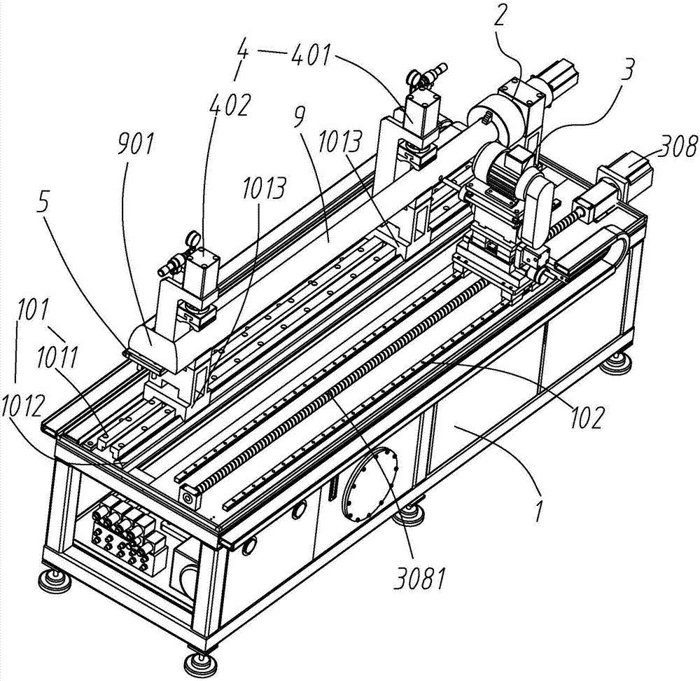
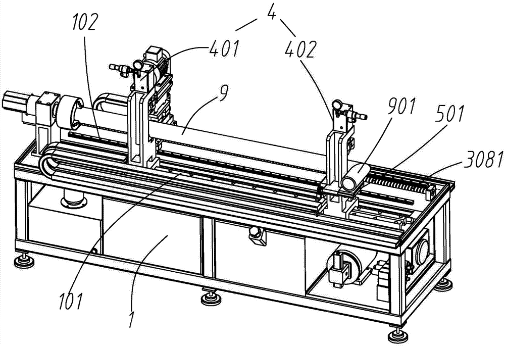
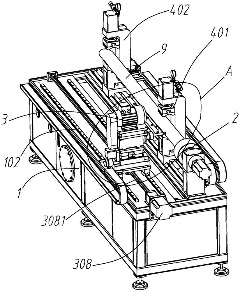
[0031] Such as Figure 1 to Figure 5 As shown, the automatic header drilling machine includes a frame 1, and the frame 1 is provided with a clamping swing angle mechanism 2, which can clamp the pipeline workpiece 9 and make the pipeline workpiece 9 rotate along its own axis The drilling mechanism 3 is located on the side of the pipeline workpiece 9 clamped by the clamping swing angle mechanism 2, and can move along the length direction of the pipeline workpiece 9 on the frame 1 and can...


PUM


Abstract

The invention relates to pipeline drilling machining, in particular to an automatic drilling machine for a flow collecting pipe. The automatic drilling machine comprises a machine frame; the machine frame is provided with a clamping swinging mechanism, a drilling mechanism, an auxiliary clamping mechanism and an auxiliary positioning mechanism, wherein the auxiliary clamping mechanism is located on the other side of a pipeline workpiece clamped by the clamping swinging mechanism and can move on the machine frame in the length direction of the pipeline workpiece, and a first auxiliary clampingmechanism body is provided with a pressing assembly capable of being pressed on the outer surface of the pipeline workpiece; and the auxiliary positioning mechanism is located on a bent section whichis on one side of the auxiliary clamping mechanism and used for supporting the pipeline workpiece, the auxiliary positioning mechanism comprises a supporting plate and a driving mechanism for drivingthe supporting plate to rotate, and after the driving mechanism drives the supporting plate to rotate, the bent section can be rotated along with the pipeline workpiece. During pipeline workpiece installation, one end of the pipeline workpiece is clamped and positioned through the clamping swinging mechanism, the bent part at the other end of the pipeline workpiece is positioned through the auxiliary positioning mechanism, the whole pipeline workpiece can be located on the horizontal plane, and accordingly the drilling machining quality is improved.

Description

【Technical field】 [0001] The invention relates to pipeline drilling, in particular to an automatic drilling machine for collecting pipes. 【Background technique】 [0002] At present, the drillers of some headers usually weld the pipe fittings at both ends at 90 degrees before drilling, and the general drilling machine usually only clamps one end of the pipe fittings for positioning. For the pipe fittings welded at 90 degrees, Because the bending section welded at the rear end affects the position of the center of gravity of the entire pipe, it is difficult to maintain the level of the pipe simply by clamping and positioning at one end, which will affect the position accuracy of the drilling and affect the quality of the drilling. 【Content of invention】 [0003] In order to solve the problem of unstable positioning of pipe fittings welded at 90° in the prior art, the present invention provides an automatic header drilling machine with a relatively simple structure. [0004]...

Claims


Application Information

Patent Timeline
IPC IPC(8): B23Q3/08
CPCB23Q3/082
Inventor 邓凯谌晓永黎宪进廖家蒙
Owner ZHONGSHAN OMS AUTOMATION EQUIP
Features
  • Generate Ideas
  • Intellectual Property
  • Life Sciences
  • Materials
  • Tech Scout
  • Unparalleled Data Quality
  • Higher Quality Content
  • 60% Fewer Hallucinations
Learn More