Launch control unmanned aerial vehicle

A technology of unmanned aerial vehicle and landing gear, applied in the field of aircraft, can solve the problems of high site requirements, inconvenient throwing and take-off, unfavorable control, etc., and achieve the effects of saving power, simple structure and long battery life

Inactive Publication Date: 2018-04-27
FOSHAN SHENHANG SCI & TECH CO LTD
View PDF0 Cites 3 Cited by
  • Summary
  • Abstract
  • Description
  • Claims
  • Application Information

AI Technical Summary

Problems solved by technology

[0002] The traditional fixed-wing aircraft model needs a flat open space to take off, and has high requirements for the site. For miniature aircr

Method used


Image

  • Launch control unmanned aerial vehicle

Examples


Embodiment Construction

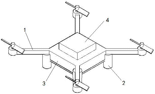
[0011] The present invention will now be described in detail with reference to the drawings. A catapult-starting drone includes a drone body 1, a landing gear 2, a high-pressure air chamber 3, and a controller 4.

[0012] The landing gear 2 is placed under the main body of the drone. There are four landing gears, which are symmetrically distributed and have the same function. The controller 4 is placed on the drone body 1. The high-pressure air cabin 3 is placed on the drone body 1 and connected to the controller 4. The inner through hole of the landing gear 2 is connected with the high-pressure air chamber 3. The inflation and deflation of the high-pressure air chamber 3 are performed through the holes of the landing gear 2.

[0013] The working process of the ejection-start UAV: ​​Inflate the high-pressure air cabin 3 through external equipment. After the inflation is completed, use the controller 4 to open the high-pressure air cabin 3, and the gas is ejected from the through ...


PUM


Abstract

The invention relates to a launch control unmanned aerial vehicle and belongs to the field of aircrafts. The launch control unmanned aerial vehicle comprises an unmanned aerial vehicle body, an undercarriage, a high-pressure gas cabin and a controller. The undercarriage is arranged below the unmanned aerial vehicle body. The controller is arranged on the unmanned aerial vehicle body. The high-pressure gas cabin is arranged on the unmanned aerial vehicle body and connected with the controller. An internal through hole of the undercarriage is connected with the high-pressure gas cabin. Accordingto the launch control unmanned aerial vehicle, the principle is simple, the structure is simple, launch control is achieved, the head-start effect is achieved, a power supply is saved, and the higherendurance ability is achieved.

Description

Technical field [0001] A catapult-starting UAV belongs to the field of aircraft, and particularly relates to a UAV. Background technique [0002] Traditional fixed-wing aircraft models require a flat area for take-off, which has high requirements on the field. For miniature aircraft, it can take off by throwing. However, larger aircraft models obviously cannot take off by throwing; and throwing takes off. Convenient, not conducive to manipulation. Summary of the invention [0003] The solution of the present invention is to invent a catapult-starting drone in order to overcome the shortcomings of the foregoing solution. [0004] A catapult-starting drone includes a drone body, a landing gear, a high-pressure air chamber and a controller. [0005] The landing gear is placed under the drone body. The controller is placed on the drone body. The high-pressure air chamber is placed on the drone body and connected with the controller. The inner through hole of the landing gear is conne...

Claims


Application Information

Patent Timeline
IPC IPC(8): B64C39/02B64C25/32B64C15/14A63H27/00A63H27/32
CPCA63H27/02B64C15/14B64C25/32B64C39/02B64U70/00
Inventor 王美航
Owner FOSHAN SHENHANG SCI & TECH CO LTD
Why Eureka
Try Eureka