Bridge wet joint cast-in-place concrete automatic vibration compacting device

A technology of vibratory compaction and wet joints, which is applied in the direction of bridge construction, bridge erection/assembly of bridges, etc. It can solve the problems of inability to ensure the compactness of concrete, holes in concrete, and inability to vibrate concrete, so as to achieve stable work and low labor intensity. Small, the effect of reducing labor intensity

Inactive Publication Date: 2018-04-27
吴丹
View PDF0 Cites 4 Cited by
  • Summary
  • Abstract
  • Description
  • Claims
  • Application Information

AI Technical Summary

Problems solved by technology

[0003] In order to solve the above problems, the present invention provides an automatic vibration compaction equipment for bridge wet joint cast-in-place concrete, which can solve the existing wet joint concrete pouring process and need to manually carry out the pouring of concrete with the existing vibration equipment. Vibration compaction, the reinforcement cage needs to be avoided during the vibration of wet joint concrete pouring, the operation is complicated, the concrete cannot be fully vibrated manually, the compactness of the concrete cannot be ensured, and the concrete will have holes, which will affect the quality of the project. It can realize the function of high-efficiency vibration compaction of wet joint concrete without manual vibration of concrete, without potential safety hazards, and has the advantages of simple operation, stable work, resource saving, low labor intensity and high work efficiency.

Method used


Image

  • Bridge wet joint cast-in-place concrete automatic vibration compacting device
  • Bridge wet joint cast-in-place concrete automatic vibration compacting device
  • Bridge wet joint cast-in-place concrete automatic vibration compacting device

Examples


Embodiment Construction

[0019] In order to make the technical means, creative features, goals and effects achieved by the present invention easy to understand, the present invention will be further described below in conjunction with specific illustrations.

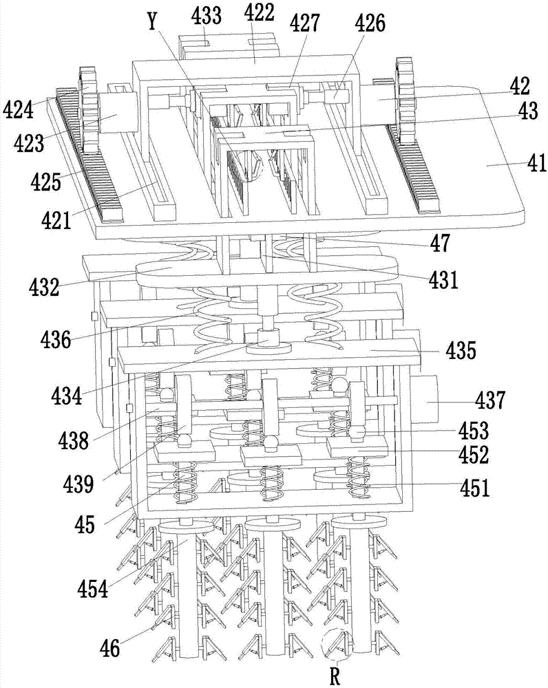
[0020] Such as Figure 1 to Figure 4 As shown, a bridge wet joint cast-in-place concrete automatic vibration compaction equipment includes a vibration support frame 41, a vibration movement mechanism 42 is arranged on the vibration support frame 41, a vibration movement groove is arranged on the vibration support frame 41, and the vibration support frame The lower end of 41 is equipped with a vibration support groove 47, and the vibration displacement mechanism 43 is arranged at equal intervals from left to right in the vibration support groove 47 through a sliding fit mode. The mechanism 42 drives the vibration-displacement mechanism 43 to make appropriate adjustments, which eliminates the need for manual vibratory compaction operations with th...


PUM


Abstract

The invention relates to an automatic vibration compaction equipment for cast-in-place concrete at bridge wet joints, comprising a vibration support frame, a vibration movement mechanism is arranged on the vibration support frame, a vibration movement groove is arranged on the vibration support frame, and a vibration movement groove is installed on the lower end of the vibration support frame. Vibration support groove, the vibration displacement mechanism is provided at equal intervals from left to right in the vibration support groove through sliding fit, and the vibration displacement mechanism is located in the vibration movement groove. The present invention can solve the problems existing in the existing concrete pouring process for wet joints that need to manually vibrate and compact the poured concrete with the help of existing vibrating equipment. During the vibration process of concrete pouring for wet joints, steel cages need to be avoided, and the operation is complicated. The concrete cannot be fully vibrated manually, and the compactness of the concrete cannot be ensured. There will be holes in the concrete, which will affect the quality of the project, and there will be safety hazards and other problems. It can realize the function of high-efficiency vibration compaction of wet joint concrete.

Description

technical field [0001] The invention relates to the technical field of road and bridge construction, in particular to an automatic vibration compaction device for cast-in-place concrete at bridge wet joints. Background technique [0002] Wet joints refer to the joints where prestressed concrete beams are prefabricated in blocks, cantilevered into large-span continuous beams, and cast-in-place concrete is used between the beams to connect the beams into a whole. In the process of wet joint construction, it is necessary to chisel the position of the joint, and weld the reinforcement cage to the position of the joint, so as to improve the construction quality of the wet joint, and then carry out the concrete pouring operation, which is an important part of the wet joint construction. In the process of pouring concrete, the concrete needs to be vibrated, but in the process of pouring concrete with wet joints, it is necessary to vibrate and compact the poured concrete manually wi...

Claims


Application Information

Patent Timeline
Patent Type & Authority Applications(China)
IPC IPC(8): E01D21/10
CPCE01D21/10
Inventor 吴丹
Owner 吴丹
Why Eureka
Try Eureka