Multi-gradient self-rotation type sand collecting instrument

A self-rotating, sand collecting instrument technology, applied in the direction of sampling devices, etc., can solve problems such as roadbed slope erosion, impact on driving safety, human society loss, etc., and achieve low cost, convenient operation, and high collection rate of sand materials.

Pending Publication Date: 2018-04-27
BEIJING JIAOTONG UNIV
View PDF7 Cites 5 Cited by
  • Summary
  • Abstract
  • Description
  • Claims
  • Application Information

AI Technical Summary

Problems solved by technology

[0002] Wind and sand disasters are the key research content in the professional field of soil and water conservation and desertification prevention and control. Wind and sand seriously affect road and railway traffic in sandy areas, which can easily ca...

Method used


Image

  • Multi-gradient self-rotation type sand collecting instrument
  • Multi-gradient self-rotation type sand collecting instrument
  • Multi-gradient self-rotation type sand collecting instrument

Examples


Embodiment 1

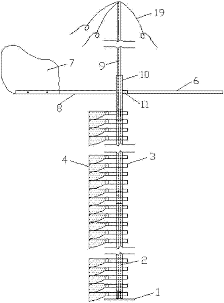
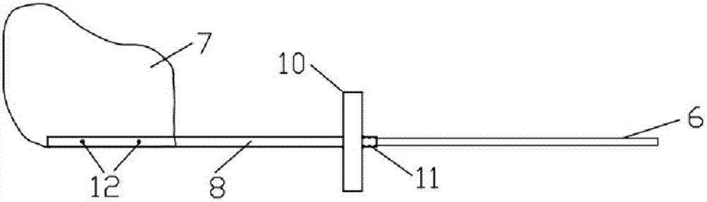
[0035] The multi-gradient self-rotating sand collection instrument described in the embodiment of the present invention, the self-rotating sand collection instrument is a detachable combined structure, figure 1 is the front view of the self-rotating sand collector, such as figure 1 Shown: including base 1, hollow column 2, sand collection unit 18, wind vane and rotating pole 9;

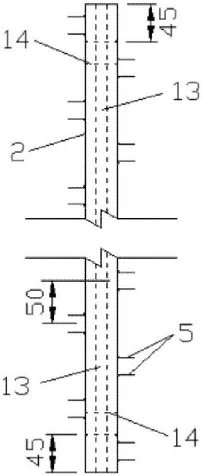
[0036] The bottom of the hollow column 2 is vertically connected with the base 1, the sand collection unit 18 is fixed on both sides of the hollow column 2, and the top of the hollow column 2 is connected with the wind vane through a connecting device 15, so that The rotating upright 9 is inserted through the hole at the top of the wind vane, and is connected with the built-in rotating shaft 13 of the hollow upright 2 .

[0037] The top of the rotating pole 9 is provided with an oblique stay rope 19 .

[0038] Described oblique stay rope 19 is in order to prevent the sand collector from toppling ove...

Embodiment 2

[0056] The embodiment of the present invention is the practical application of the self-rotating sand collector, which is detailed as follows:

[0057] a. The sand collection box 3 and the sand collection bag 4 are bound indoors (the whole is called the sand collection unit 18), and they are assembled into boxes, with 43 sand collection units 18 in each group, and the sand inlet of the sand collection box 3 faces downward. Place them to prevent sundries from entering the sand-collecting bag 4, and number them sequentially. The labels can be pasted on the sand-collecting box 3, and the box is sealed and dust-proof;

[0058] b. When there are wind and sand activities on the surface, assemble the sand collection instrument at the predetermined observation position, and finally install the sand collection unit 18. When installing the sand collection box 3 to the buckle 5, quickly install it according to the number from top to bottom or bottom to top At the same time, make the sand...


PUM


Abstract

The invention provides a multi-gradient self-rotation type sand collecting instrument. The multi-gradient self-rotation type sand collecting instrument is characterized in that the multi-gradient self-rotation type sand collecting instrument is of a detachable combined type structure, a rotary shaft which is arranged in a hollow upright column is inserted into a shaft sleeve on a base, a wind vaneis connected with the top of the hollow upright column by a built-in sleeve, a rotary upright rod is inserted into a hollow pipe of the wind vane via a circular hole in the top of the hollow pipe, the bottom of the rotary upright rod sleeves the rotary shaft arranged in the upright column, oblique stays are mounted on the top of the rotary upright rod, a plurality of buckles are equidistantly welded on two sides of the upright column in a staggered manner, sand collecting boxes are fixed to the two sides of the upright column by the aid of the buckles, and a sand collecting bag is fixed to anend of a leeward opening of each sand collecting box. The multi-gradient self-rotation type sand collecting instrument has the advantages that the multi-gradient self-rotation type sand collecting instrument which is an observation device is simple in structure and convenient to disassemble, and the near-ground wind-sand flow and sand-transport quantities can be accurately and quickly observed bythe aid of the multi-gradient self-rotation type sand collecting instrument.

Description

technical field [0001] The invention relates to the technical field of soil and water conservation and desertification prevention and control, in particular to a multi-gradient self-rotating sand collector. Background technique [0002] Wind and sand disasters are the key research content in the professional field of soil and water conservation and desertification prevention and control. Wind and sand seriously affect road and railway traffic in sandy areas, which can easily cause erosion of roadbed slopes, and also easily generate wind and sand accumulation at the foot of the roadbed slope and the top of the roadbed, affecting driving safety. Seriously, it will lead to traffic interruption and cause huge losses to human society. Practice has shown that most of the sand in the sand flow passes close to the ground. How to conduct accurate observations of the near-surface sand flow through scientific instruments, so as to fully grasp the structural characteristics of the wind ...

Claims


Application Information

Patent Timeline
IPC IPC(8): G01N1/20
CPCG01N1/20
Inventor 刘世海刘莹陈祥王连俊许兆义沈宇鹏王勐罗国才
Owner BEIJING JIAOTONG UNIV
Why Eureka
Try Eureka