Electromagnetic slope loading test device and loading method

A loading test device and loading device technology, applied in the direction of measuring devices, using stable tension/pressure testing material strength, instruments, etc., can solve the problems of uneven loading, stress concentration, etc., and achieve simple structure, high use efficiency, Ease of use

Inactive Publication Date: 2018-04-27
CHINA UNIV OF MINING & TECH (BEIJING)
View PDF5 Cites 2 Cited by
  • Summary
  • Abstract
  • Description
  • Claims
  • Application Information

AI Technical Summary

Problems solved by technology

At present, the slope model test uses the bearing plate to load, but there are phenomena such as une

Method used


Image

  • Electromagnetic slope loading test device and loading method
  • Electromagnetic slope loading test device and loading method
  • Electromagnetic slope loading test device and loading method

Examples


Embodiment 1

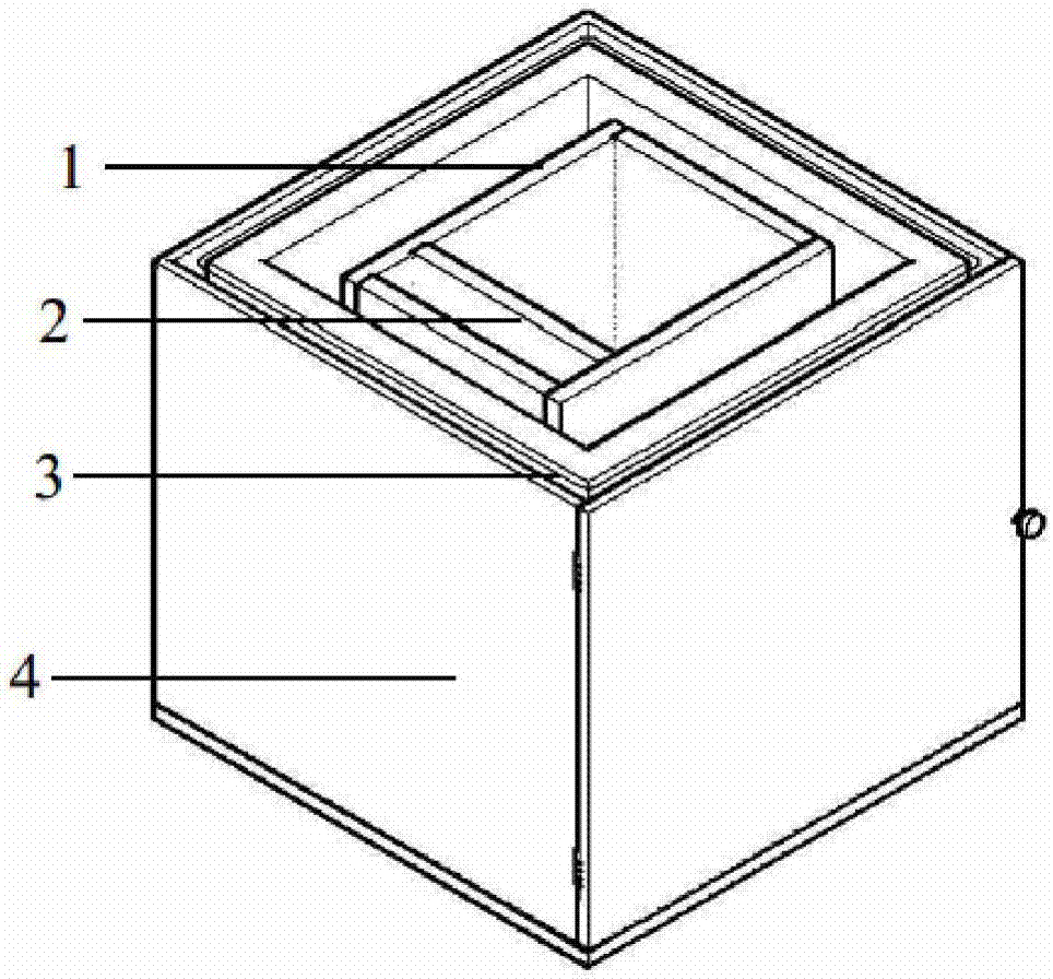
[0032] Embodiment 1: as figure 1 , figure 2 , image 3 , Figure 4 and Figure 5 As shown, an electromagnetic slope loading test device is composed of a slope model box 1, a horizontal clamping device 2, an electromagnetic force loading device 3 and an outer shell 4. The slope model box 1 is composed of tempered glass plates Box structure, length x width x height = 1.2m x 1.0m x 1.0m.

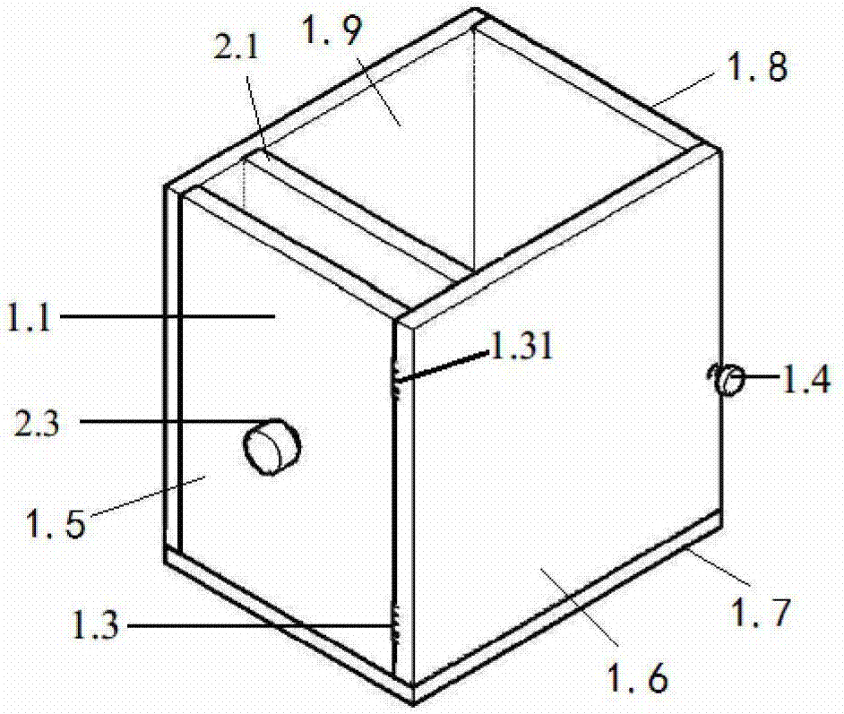
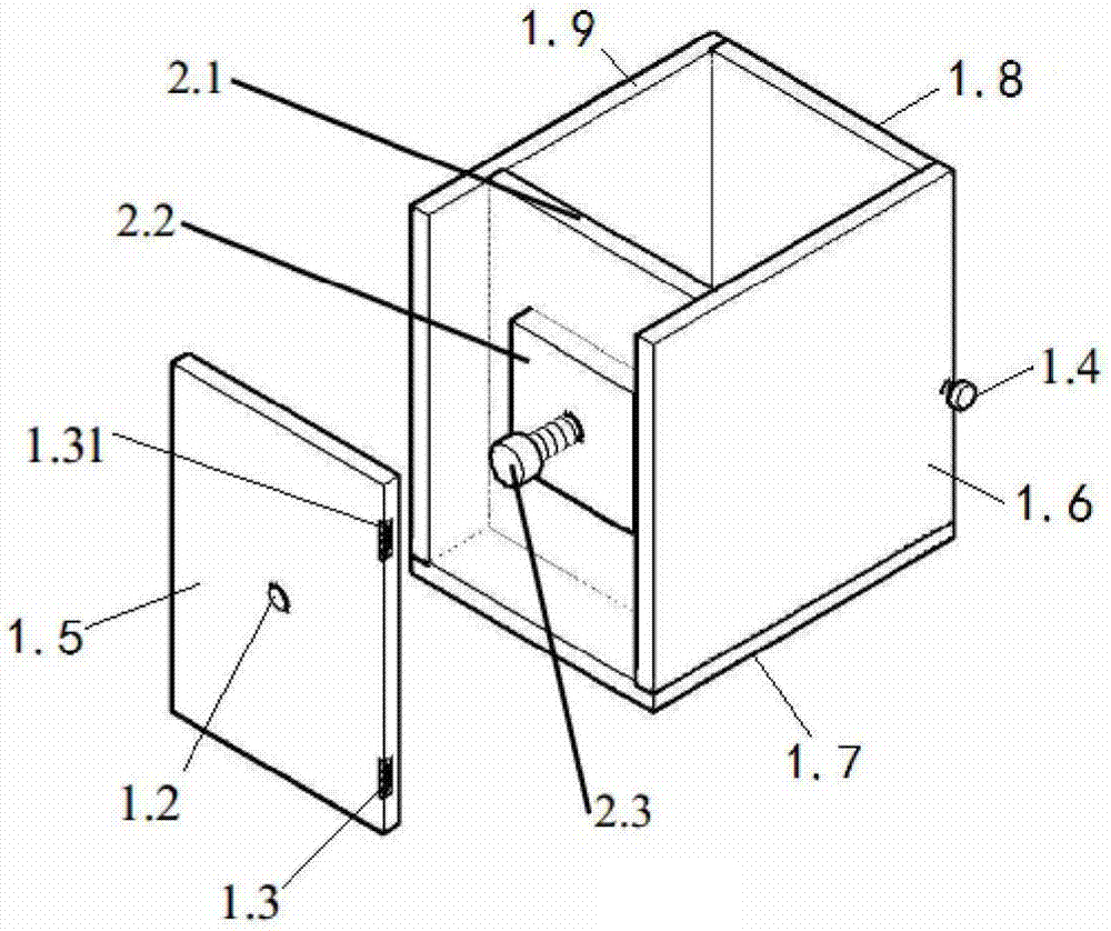
[0033] An electromagnetic force loading device 3 is placed in the inner cavity of the outer shell 4, and the slope model box 1 is placed in the inner cavity of the electromagnetic force loading device 3, and the horizontal clamping device 2 is placed in the inner cavity of the slope model box 1, and the slope model box 1 includes Tempered glass plate 1.1, internal threaded hole 1.2, first hinge 1.3 and first fixing bolt 1.4, horizontal clamping device 2 includes clamping plate 2.1, connecting block 2.2 and horizontal clamping bolt 2.3,

[0034] The bottom plate 1.7, the left side panel 1....

Embodiment 2

[0037] Embodiment 2: asfigure 1 , figure 2 , image 3 , Figure 4 and Figure 5 Shown is an electromagnetic slope loading test device and loading method. This experimental device is mainly used for the loading test of the slope model. It can load different electromagnetic forces on the slope model containing iron granular. It is mainly composed of It consists of four parts: a slope model box 1, a horizontal clamping device 2, an electromagnetic force loading device 3 and an outer casing 4.

[0038] The slope model box 1 includes a tempered glass plate 1.1, an internal threaded hole 1.2, a first hinge 1.3 and a first fixing bolt 1.4,

[0039] figure 2 It is a schematic diagram of the structure of the slope model box. The slope model box is a box structure composed of tempered glass plates, and the length × width × height = 1.2m × 1.0m × 1.0m. Both the bottom plate and the side panels are tempered glass plates 1.1; the internal threaded hole 1.2 is located in the middle o...


PUM


Abstract

Belonging to the technical field of machinery, the invention relates to an electromagnetic slope loading test device and a loading method. An electromagnetic force loading apparatus is placed in the cavity of an outer shell, a slope model box is placed in the cavity of the electromagnetic force loading apparatus, a horizontal clamping apparatus is placed in the cavity of the slope model box, an inner threaded hole is located at the center of the slope model box's front panel, a horizontal clamping bolt is connected to the inner threaded hole through a thread and passes through the inner threaded hole, the thread end of the horizontal clamping bolt and the inner threaded hole of a connection block are in fixed connection. A clamping plate is connected to the cavity of the slope model box, the connection block is located between the front panel and the clamping plate, the right panel of the slope model box is connected to the front panel through a first hinge and a second hinge. And theright panel of the slope model box and a rear panel are connected together through a first fixed bolt. The electromagnetic slope loading test device provided by the invention has the characteristics of simple structure and convenient use, and can accurately simulate the stability condition of slope under the action of self weight or other external load.

Description

technical field [0001] The invention relates to an electromagnetic slope loading test device and a loading method, which belong to the technical field of machinery. Background technique [0002] Under the action of self-weight or other external loads, landslides often occur on slopes, which pose a serious threat to national property and people's lives. With the vigorous development of infrastructure in our country, a large number of slope stability problems are involved in mines, water conservancy and transportation. Therefore, it is very necessary to study the stability of slopes under the action of self-weight or other external loads. At present, the slope model test uses the bearing plate to load, but there are phenomena such as uneven loading and stress concentration, so there are still shortcomings in simulating the gravity field. Contents of the invention [0003] In order to overcome the deficiencies of the prior art, the present invention provides an electromagne...

Claims


Application Information

Patent Timeline
IPC IPC(8): G01N3/08G01N3/02
Inventor 孙书伟王玉凯庞博马宁梁伟新张震
Owner CHINA UNIV OF MINING & TECH (BEIJING)
Why Eureka
Try Eureka