Stator winding structure and motor

A stator winding and fixed structure technology, applied to the shape/style/structure of the winding conductor, can solve the problems of increasing the bearing distance, increasing the axial distance of the motor, and the small critical speed of the rotor, so as to reduce the volume and increase the speed , to ease the effect of the critical speed

Pending Publication Date: 2018-04-27
博远机电(嘉兴)有限公司
View PDF10 Cites 0 Cited by
  • Summary
  • Abstract
  • Description
  • Claims
  • Application Information

AI Technical Summary

Problems solved by technology

[0003] However, the ends of the existing motor windings are too long, so that the occupied space at both ends of the stator core is large, the bearing distance is increased, the axial distance of the motor is increased, and the critical speed of the rotor is small, which not only affects the speed of the motor, but also The size of the motor is also too large

Method used


Image

  • Stator winding structure and motor
  • Stator winding structure and motor
  • Stator winding structure and motor

Examples


Embodiment 1

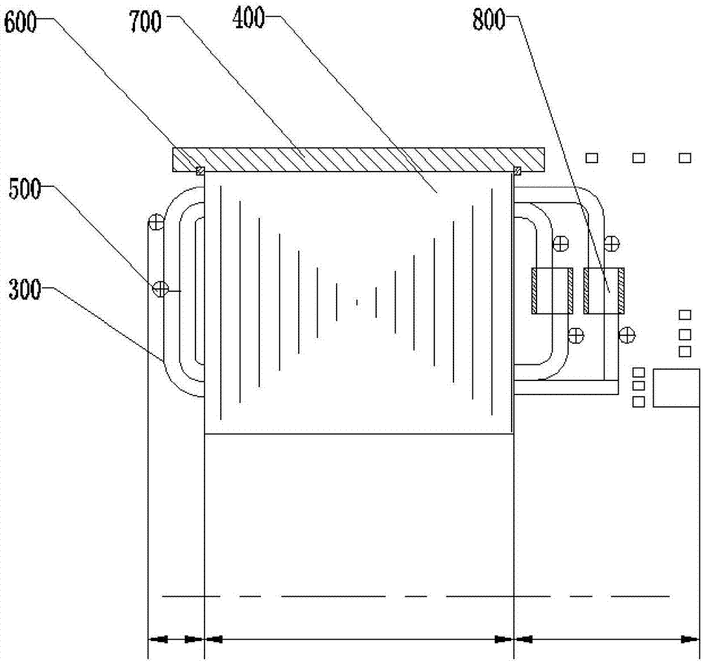
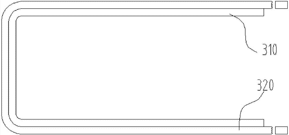
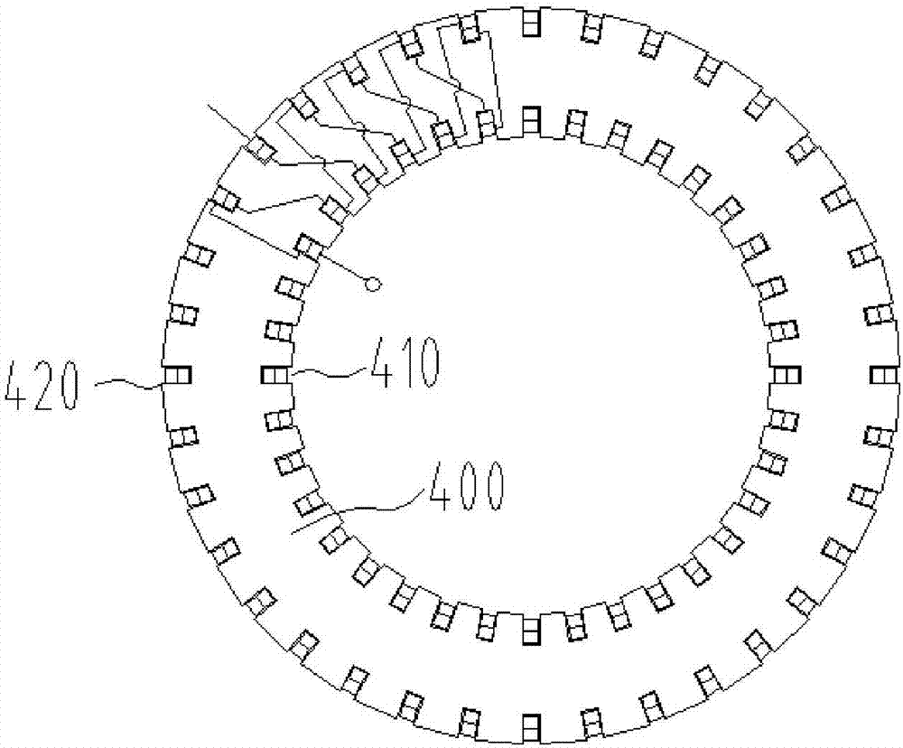
[0036] Such as Figure 1-Figure 3 As shown, the stator winding structure provided by this embodiment includes a stator core, a stator coil 300, and a fixing structure 500 for fixing the stator coil 300 on the side wall of the stator core; the stator coil 300 is arranged as a U-shaped structure, and can be The iron core 400 is inserted into and penetrates the side wall of the stator iron core 400 in the length direction; multiple sets of stator coils 300 are provided, and one end of any adjacent two sets of stator coils 300 is connected by a joint 800; the winding method of the stator coil 300 is to pass through the stator iron core The inner diameter of 400 to the outer diameter of the stator core 400 includes the stator core 400.

[0037] In this embodiment, the U-shaped stator coil 300 includes a first side and a second side opposite to the first side; the first side and the second side of the stator coil 300 are respectively bent by 90°, And it is connected with the bent f...

Embodiment 2

[0050] The motor provided in this embodiment includes the above-mentioned stator winding structure.

[0051] The motor provided in this embodiment includes the above-mentioned stator winding structure. Due to the setting of the stator winding structure, the motor has all the advantages of the above-mentioned material distribution mechanism, which can alleviate the technical problems that the end of the winding is too long, the axial distance of the motor is increased, and the critical speed of the rotor is reduced; the invention improves the motor speed. speed, reduce the size of the motor.


PUM


Abstract

The invention relates to the technical field of motors, in particular to a stator winding structure and a motor. The stator winding structure is characterized in that the stator winding structure comprises a stator core, stator coils and a fixing structure which is used for fixing the stator coils on the side wall of the stator core; the stator coils are arranged to be of a U-shaped structure andcapable of inserting and penetrating the side wall of the stator core along the length direction of the stator core; multiple sets of stator coils are arranged, and one ends of any two adjacent sets of the stator coils are connected through a joint; the stator coils are wound in the way that the stator coils pass through the inside diameter of the stator core and reach the outside diameter of thestator core to wrap around the stator core. The motor comprises the stator winding structure. The stator winding structure has the advantages of alleviating the problem of too long end portion of stator winding, increasing the axial distance of the motor, and thereby solving the technical problem of reducing the critical speed of a rotor. Furthermore, motor speed is increased, and the volume of the motor is reduced.

Description

technical field [0001] The invention relates to the technical field of motors, in particular to a stator winding structure and a motor. Background technique [0002] With the development of the electric power industry, the application of motors at home and abroad is becoming more and more extensive. Some loads have higher requirements on the speed. However, increasing the speed of the motor will have higher requirements on the performance of the motor. The existing motor Performance is difficult to meet such high requirements. At present, the stacked winding in the stator winding is generally composed of coils of the same shape and size, one or two coil sides are embedded in each slot, and the outer ends of the slots are stacked one by one and evenly distributed. [0003] However, the ends of the existing motor windings are too long, so that the occupied space at both ends of the stator core is large, the bearing distance is increased, the axial distance of the motor is inc...

Claims


Application Information

Patent Timeline
Patent Type & Authority Applications(China)
IPC IPC(8): H02K3/04H02K3/28
CPCH02K3/04H02K3/28
Inventor 张永生吴兴刚邹建华郑军铭唐湘博
Owner 博远机电(嘉兴)有限公司
Why Eureka
Try Eureka