Multi-module-series-circuit-based module self-power-taking and protection circuit

A technology of series circuit and protection circuit, which is applied in the field of module self-collection and protection circuit, can solve the problems of increasing the insulation requirements of the power supply, the voltage drop of the power supply, and the system paralysis.

Inactive Publication Date: 2018-04-27
INST OF ELECTRICAL ENG CHINESE ACAD OF SCI
View PDF2 Cites 2 Cited by
  • Summary
  • Abstract
  • Description
  • Claims
  • Application Information

AI Technical Summary

Problems solved by technology

[0002] At present, regardless of the multi-module input series output parallel circuit or the multi-module input parallel output series circuit, the voltage level of the series part is relatively high, and each module uses an uncontrolled bridge circuit and a controllable bridge circuit plus a high-voltage high-frequency transformer for isolation and transformation. , if the input of the power supply is directly connected to the multi-module series circuit, it will inevitably increase the insulation requirements of the power supply and increase the design difficulty of the power supply
At the same time, any module in the multi-module series circuit has an open circuit fault, so that the entire series circuit system has no current loop and cannot work normally, and the entire system is paralyzed.
[0003] For the above-mentioned problem of taking power

Method used


Image

  • Multi-module-series-circuit-based module self-power-taking and protection circuit
  • Multi-module-series-circuit-based module self-power-taking and protection circuit

Examples


Example Embodiment

[0014] The present invention will be further described below in conjunction with the drawings and specific embodiments.

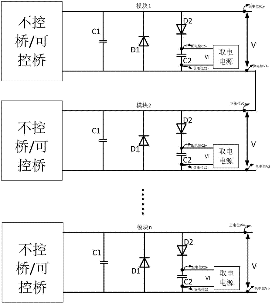
[0015] The multi-module series circuit mainly refers to the output circuit part in the multi-module input parallel output series and the input circuit part in the multi-module input series output parallel connection. It is composed of n identical modules in series, n≥1, such as figure 2 Shown.

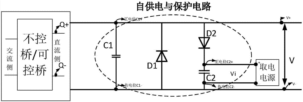
[0016] Such as figure 1 As shown, the module self-acquisition and protection circuit of the multi-module series circuit of the present invention is mainly composed of a capacitor C1, a diode D1, a diode D2, and a capacitor C2. The diode D2 is connected in series with the capacitor C2 to form a self-powering circuit of the module. The cathode of the diode D2 is connected to the positive potential C2+ of the capacitor C2, the capacitor C1 is connected in parallel with the diode D1, the cathode of the diode D1 is connected with the anode of the diode D2, and the positive p...


PUM


Abstract

The invention relates to a multi-module-series-circuit-based module self-power-taking and protection circuit comprising a capacitor C1, a diode D1, a diode D2, and a capacitor C2. The diode D2 is connected in series with the capacitor C2 to form a module self-power-taking circuit; a cathode of the diode D2 is connected with a positive potential point C2+ of the capacitor C2; the capacitor C1 is connected in parallel to the diode D1; and a cathode of the diode D1 is connected with an anode of the diode D2, a positive potential point C1+ of the capacitor C1, and a positive potential point V+ ofa module. A negative potential point C1- of the capacitor C1 is connected to an anode of the diode D1, a negative potential point C2 of the capacitor C2, and a negative potential point V- of the module; a positive potential point Q+ of a non-controlled bridge/controllable bridge circuit direct-current side is connected with the positive potential point V+ of the module; a negative potential pointQ- of the non-controlled bridge/controllable bridge circuit direct-current side is connected with the negative potential point V- of the module; a positive potential point C2+ of the capacitor C2 is connected with a positive potential point V+ of a power-taking power supply; and a negative potential point C2- of the capacitor C2 is connected with a negative potential point - of the power-taking power supply.

Description

technical field [0001] The invention relates to a module self-feeding and protection circuit of a multi-module series circuit. Background technique [0002] At present, regardless of the multi-module input series output parallel circuit or the multi-module input parallel output series circuit, the voltage level of the series part is relatively high, and each module uses an uncontrolled bridge circuit and a controllable bridge circuit plus a high-voltage high-frequency transformer for isolation and transformation. , if the input of the power supply is directly connected to the multi-module series circuit, the insulation requirements of the power supply will inevitably be increased, and the design difficulty of the power supply will be increased. At the same time, any module in the multi-module series circuit has an open circuit fault, so that the entire series circuit system has no current loop and cannot work normally, and the entire system is paralyzed. [0003] For the ab...

Claims


Application Information

Patent Timeline
IPC IPC(8): H02M1/32H02M7/04
CPCH02M1/32H02M7/04H02M1/325
Inventor 刘润彪王环鞠昌斌王一波
Owner INST OF ELECTRICAL ENG CHINESE ACAD OF SCI
Why Eureka
Try Eureka