Control system and method of electric compressor of new energy automobile
A technology for electric compressors and new energy vehicles, used in vehicle components, heating/cooling equipment, air handling equipment, etc., can solve problems such as unstable compressor operation, improve good experience, increase mileage, and improve control. The effect of precision
- Summary
- Abstract
- Description
- Claims
- Application Information
AI Technical Summary
Problems solved by technology
Method used
Image
Examples
Embodiment 1
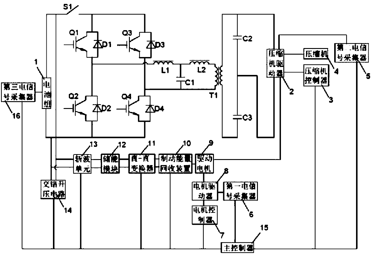
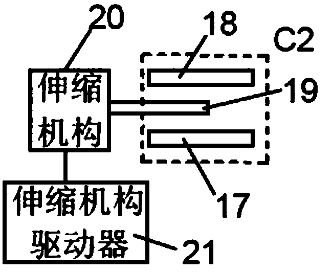
[0039] The present invention provides an electric compressor control system for a new energy vehicle, such as Figure 1-3 As shown, it includes an inverter module, a transducer module, a voltage divider module and a voltage stabilization control unit.
[0040] The input terminal of the inverter module is connected to the output terminal of the battery pack 1 through the controllable switch S1. In this embodiment, the inverter module is composed of four IGBTs, including the first switching tube Q1 to the fourth switching tube Q4 and the first Diode D1 to the fourth diode D4, the input terminal of the transduction module is connected to the output terminal of the inverter module, and the transduction module is a step-up transformer T1, which plays the role of voltage isolation and boosting, so The primary coil of the step-up transformer is connected to the output terminal of the inverter module through a filter, and the filter is an LCL filter including a first inductor L1, a se...
Embodiment 2
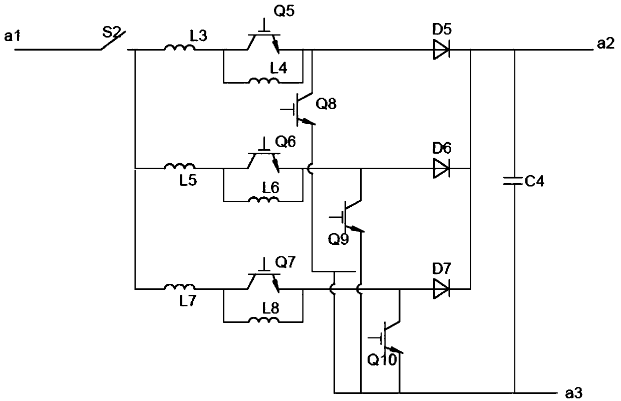
[0053] The interleaved boosting circuit 14 includes a first boosting branch, a second boosting branch, a third boosting branch and a fourth capacitor C4 arranged at the output end of the interleaving boosting circuit 14 arranged in parallel.
[0054] The first step-up branch includes a third inductor L3, a fifth switching tube Q5, a fourth inductor L4, a fifth diode D5, and an eighth switching tube Q8, and the third inductor L3, the fifth switching tube Q5 connected in series with the second pentode D5 at the positive terminal of the battery pack 1, the fourth inductance L4 is connected in parallel with both ends of the fifth switching tube Q5, and the input terminal of the eighth switching tube Q8 is connected to the The output terminal of the fifth switching tube Q5; the second boosting branch includes a fifth inductor L5, a sixth switching tube Q6, a sixth inductor L6, a sixth diode D6 and a ninth switching tube Q9, the first The fifth inductor L5, the sixth switching tube ...
Embodiment 3
[0058] A method for controlling an electric compressor of a new energy vehicle, comprising the following steps:
[0059] Step 1, the third electrical signal collector 16 collects the voltage signal of the output terminal of the battery pack 1 in real time and transmits it to the main controller 15 to monitor the output voltage of the battery pack. When the motor starts, accelerates and stops, it will cause large fluctuations in the output voltage of the battery pack, affecting the normal operation of the compressor, causing the air conditioning system to be hot and cold, and affecting the passenger experience. For this reason, when the output terminal voltage of the battery pack 1 fluctuates momentarily, the main controller 15 collects the feedback signal according to the third electrical signal collector 16 and simultaneously collects the electrical signal on the motor driver 8 according to the first signal collector 6, The main controller performs intervention control in adv...
PUM
 Abstract
Description
Claims
Application Information
 - R&D
- Intellectual Property
- Life Sciences
- Materials
- Tech Scout
- Unparalleled Data Quality
- Higher Quality Content
- 60% Fewer Hallucinations
Browse by: Latest US Patents, China's latest patents, Technical Efficacy Thesaurus, Application Domain, Technology Topic, Popular Technical Reports.
© 2025 PatSnap. All rights reserved.Legal|Privacy policy|Modern Slavery Act Transparency Statement|Sitemap|About US| Contact US: help@patsnap.com


