Communication apparatus and control method thereof

a communication apparatus and control method technology, applied in the direction of safety/protection circuits, wireless communication, transportation and packaging, etc., can solve the problems of circuit shutdown, repeating shutdown and activation of circuits, and circuits may shut down, so as to suppress unstable operations of circuits and stabilize the input voltage of power receiving apparatuses.

Active Publication Date: 2020-01-28
CANON KK
View PDF8 Cites 1 Cited by
  • Summary
  • Abstract
  • Description
  • Claims
  • Application Information

AI Technical Summary

Benefits of technology

[0006]The present invention has been made in consideration of the aforementioned problems, and realizes a technique that can stabilize the input voltage of a power receiving apparatus by suppressing unstable operations of a circuit in which a transient phenomenon could possibly occur when the power receiving apparatus wirelessly receives power from another apparatus.
[0010]According to the present invention, the input voltage of a power receiving apparatus can be stabilized by suppressing unstable operations of a circuit in which a transient phenomenon could possibly occur when the power receiving apparatus wirelessly receives power from another apparatus.

Problems solved by technology

If the transient phenomenon causes application of voltage that exceeds an operating range of the circuit of the power receiving apparatus, the circuit may shut down due to its protection function, and an oscillation phenomenon whereby shutdown and activation of the circuit are repeated may occur.
If the oscillation phenomenon has occurred, several problems arise, such as the extension of a charging period caused by the suspension of a charging operation, and irregular flashing of a charging display indicator which makes it difficult to grasp an operation state.
However, if the transient phenomenon has occurred due to a fluctuation in power transmitted / received between the power transmitting apparatus and the power receiving apparatus or due to displacement of the power transmitting apparatus and the power receiving apparatus, it is desirable to stabilize the circuit voltage in response to the transient phenomenon because, in some cases, making power adjustment cannot solve the transient phenomenon in time.
However, neither Japanese Patent Laid-Open No. 2013-150534 nor Japanese Patent Laid-Open No. 2014-082864 considers the possibility of the occurrence of a transient phenomenon due to displacement and a fluctuation in transmitted / received power.

Method used


Image

  • Communication apparatus and control method thereof
  • Communication apparatus and control method thereof
  • Communication apparatus and control method thereof

Examples


first embodiment

[0025]The following describes a non-contact power supply system including a power transmitting apparatus and a power receiving apparatus according to the present embodiment.

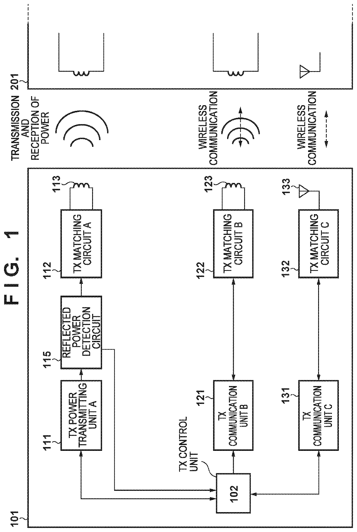
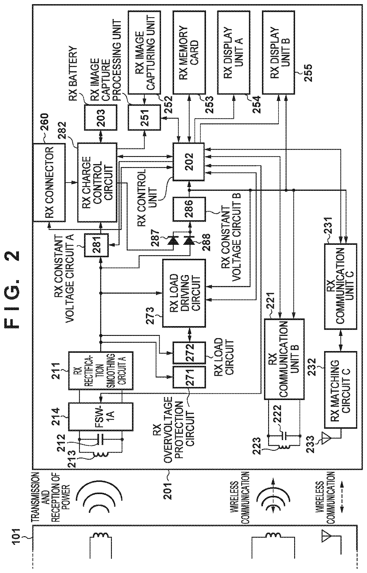
[0026]FIG. 1 is a block diagram showing an exemplary configuration of the power transmitting apparatus according to the present embodiment. FIG. 2 is a block diagram showing an exemplary configuration of the power receiving apparatus according to the present embodiment.

[0027]The non-contact power supply system according to the present embodiment includes a power transmitting apparatus 101 and a power receiving apparatus 201 that communicates with the power transmitting apparatus 101 and receives power supplied thereto. When the power receiving apparatus 201 is present within a predetermined range, the power transmitting apparatus 101 receives a connection signal containing apparatus information from the power receiving apparatus 201 via non-contact communication. Upon determining that power can be supplied to the...

second embodiment

[0197]A second embodiment will now be described using FIGS. 9 and 10.

[0198]In the first embodiment, wireless communication and wireless power transmission / reception are performed between the power transmitting apparatus 101 and the power receiving apparatus 201, and when the voltage of the output unit of the circuit that rectifies and smoothes wireless power in the power receiving apparatus 201 has increased or fluctuated, processing for stabilizing the voltage of the output unit is executed.

[0199]In the second embodiment, when the voltage of an output unit of a circuit that rectifies and smoothes wireless power in a power receiving apparatus 901 has increased or fluctuated, processing for stabilizing the voltage of the output unit is executed; note that the power receiving apparatus 901 is the same as the power receiving apparatus 201 according to the first embodiment, except that it does not include the RX constant voltage circuit A 281.

[0200]FIG. 9 is a block diagram showing an e...

third embodiment

[0241]A third embodiment will now be described using FIGS. 11A, 11B and 12.

[0242]In the first embodiment, wireless communication and wireless power transmission / reception are performed between the power transmitting apparatus 101 and the power receiving apparatus 201, and when the voltage of the output unit of the circuit that rectifies and smoothes wireless power in the power receiving apparatus 201 has increased or fluctuated, processing for stabilizing the voltage of the output unit is executed.

[0243]In the second embodiment, when the voltage of the output unit of the circuit that rectifies and smoothes wireless power in the power receiving apparatus 901 has increased or fluctuated, processing for stabilizing the voltage of the output unit is executed; note that the power receiving apparatus 901 is the same as the power receiving apparatus 201 according to the first embodiment, except that it does not include the RX constant voltage circuit A 281.

[0244]The third embodiment pertai...


PUM


Abstract

A communication apparatus, comprises a power receiving unit configured to be capable of wirelessly receiving power from another apparatus, a charging unit configured to be capable of charging a secondary battery using the power received from the another apparatus, a wireless communication unit configured to be capable of performing wireless communication with the another apparatus, a rectification smoothing unit configured to rectify and smooth the power received from the another apparatus, and output the rectified and smoothed power, a suppressing unit configured to suppress a transient voltage fluctuation in an output voltage of the rectification smoothing unit, and a driving unit configured to drive the suppressing unit so that the output voltage of the rectification smoothing unit generated by the power received from the another apparatus does not exceed a first voltage.

Description

BACKGROUND OF THE INVENTIONField of the Invention[0001]The present invention relates to a non-contact power supply system.Description of the Related Art[0002]In a non-contact power supply system, a battery inside an apparatus can be charged through wireless power supply without establishing wired connection with an external apparatus. In wireless power supply, power is transmitted and received in such a manner that an antenna of a power receiving apparatus receives electromagnetic waves emitted by an antenna of a power transmitting apparatus. In power transmission / reception between the power transmitting apparatus and the power receiving apparatus, power transmitted by the power transmitting apparatus is controlled in accordance with power required by the power receiving apparatus. There is a known phenomenon whereby, depending on the distance between and the positions of the antennas of the power transmitting apparatus and the power receiving apparatus, transmitted / received power p...

Claims


Application Information

Patent Timeline
Patent Type & Authority Patents(United States)
IPC IPC(8): H02J7/00H02J50/12H04W84/10H02J7/02
CPCH02J50/80H04W84/10H02J50/10H02J50/12H02J7/00302H02J7/00308
Inventor KAECHI, SHUYA
Owner CANON KK
Why Eureka
Try Eureka