Adjustable forestry log cutting device
A cutting device and adjustable technology, applied in the direction of circular saws, sawing equipment, wood processing equipment, etc., can solve the problems of inability to adjust the cutting depth, poor adjustability, and low efficiency of the cutting process, so as to improve cleanliness and improve Cutting effect, effect of increasing stability
- Summary
- Abstract
- Description
- Claims
- Application Information
AI Technical Summary
Problems solved by technology
Method used
Image

Examples
Embodiment Construction
[0018] Below in conjunction with specific embodiment, the technical scheme of this patent is described in further detail:
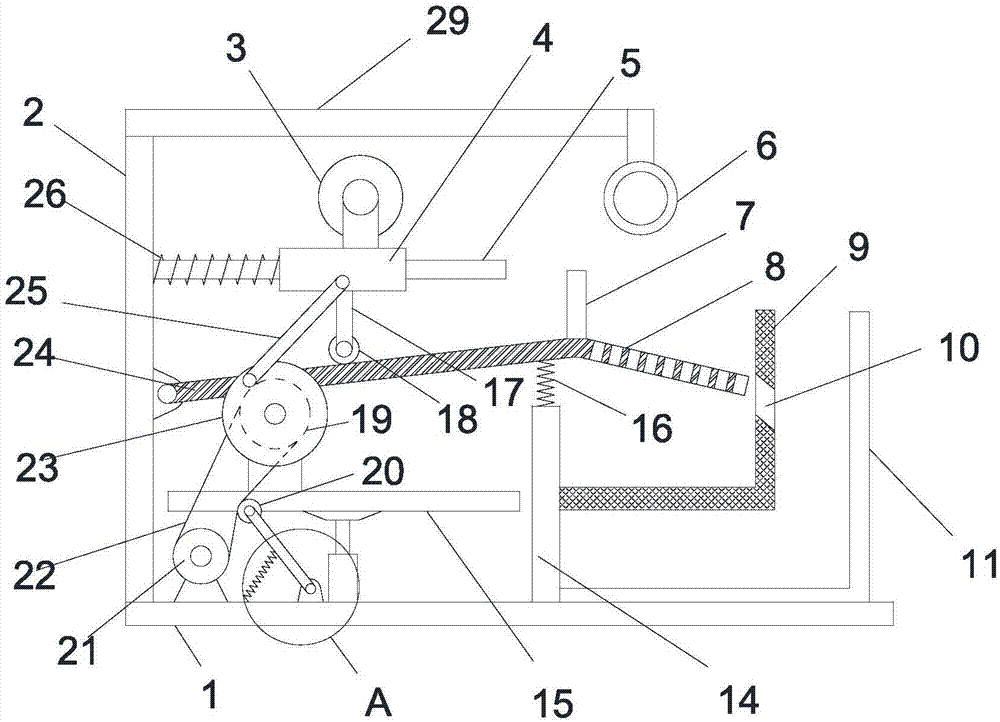
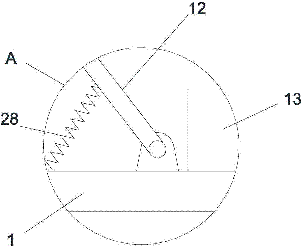
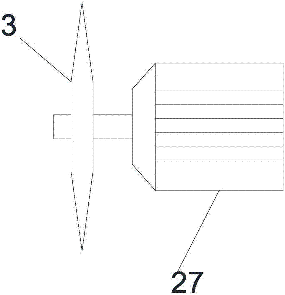
[0019] see Figure 1-3 , an adjustable log cutting device for forestry, comprising a base plate 1, a left vertical plate 2 and a right vertical plate 14 are vertically and fixedly installed on the base plate 1, a horizontal plate 29 is fixedly installed on the upper end of the left vertical plate 2 horizontally, the left On the left side wall of the vertical plate 2, a guide rod 5 is fixedly extended horizontally to the right, and a sliding sleeve 4 is provided in the guide rod 5, and a rotating motor 27 is fixedly installed on the upper end of the sliding sleeve 4, and a cutting blade 3 is installed on the rotating motor 27 The right side wall of the left vertical plate 2 is hinged with a swinging plate 24 inclined to the upper right, the right end of the swinging plate 24 is located above the right vertical plate 14, and a vibration spring 16 is connect...
PUM
 Abstract
Description
Claims
Application Information
 - R&D
- Intellectual Property
- Life Sciences
- Materials
- Tech Scout
- Unparalleled Data Quality
- Higher Quality Content
- 60% Fewer Hallucinations
Browse by: Latest US Patents, China's latest patents, Technical Efficacy Thesaurus, Application Domain, Technology Topic, Popular Technical Reports.
© 2025 PatSnap. All rights reserved.Legal|Privacy policy|Modern Slavery Act Transparency Statement|Sitemap|About US| Contact US: help@patsnap.com