
Rotation lock structure used for car seat

A car seat and rotary lock technology, which is applied in the field of rotary locks, can solve the problems of heavy rotary lock mechanism and many parts, and achieve the effect of reducing weight, reducing cost and reducing the risk of not locking

Active Publication Date: 2018-05-01
KEIPER SEATING MECHANISMS CO LTD
View PDF9 Cites 2 Cited by
  • Summary
  • Abstract
  • Description
  • Claims
  • Application Information

AI Technical Summary

Problems solved by technology

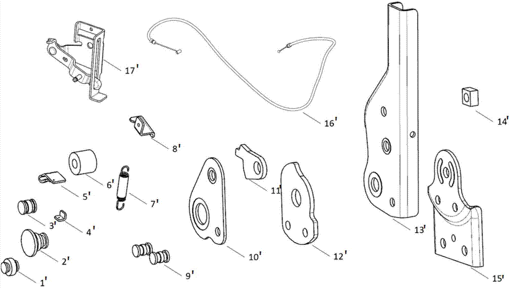
[0004] 1) There are many parts. If you count the upper bracket plate, lower bracket plate and nuts, there are 17 parts in total;
[0005] 2) The rotary lock mechanism is relatively heavy as a whole, and the total weight of all parts is nearly 1500 grams

Method used


Image

  • Rotation lock structure used for car seat
  • Rotation lock structure used for car seat
  • Rotation lock structure used for car seat

Examples


Embodiment 1

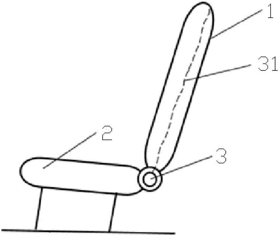
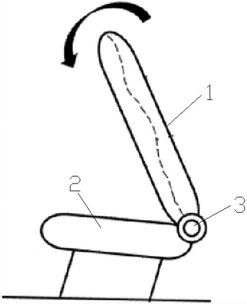
[0042] refer to Figure 2-6 As shown, the rotary lock structure for the car seat of the present invention, the car seat includes a backrest 1 and a seat cushion 2, the backrest 1 and the seat cushion 2 are rotationally connected by a rotary lock 3, and the rotary lock 3 includes a zipper mechanism 31, a lower bracket plate 32 , the upper bracket plate 33 and the rotary lock body 34, the lower bracket plate 32 is connected with the seat cushion 2, and the upper bracket plate 33 is connected with the backrest 1, wherein the rotary lock body 34 includes a cover plate 341, a guide plate 342, a pull rod 343, a lock plate 344, spring 345 and tooth plate 346;

[0043] The inside of the guide plate 342 is provided with a chute 347 and a mounting groove 348 which communicate with each other, the locking plate 344 is set in the chute 347, the spring 345 is set in the mounting groove 348, and the spring 345 is also in contact with the locking plate 344;

[0044] Tooth plate 346 fits on ...

Embodiment 2

[0062] The difference between the second embodiment and the first embodiment is:

[0063] refer to Figure 11-17 As shown, the bottom of the seat cushion 2 is also provided with a support rod 4, the support rod 4 is rotationally connected with the seat cushion 2, the cable switch 312 is arranged in the support rod 4, and the locking groove 349 includes a third locking groove 3493, when the support rod 4 When turning over, the cable switch 312 pulls the lock plate 344 through the cable 313 to retract to the inside of the chute 347, and the guide plate 342 can rotate relative to the tooth plate 346. When the support rod 4 is in use, the lock plate 344 moves along the radial direction. Slide outside the third locking groove 3493.

[0064] In this embodiment, the assembly process of the rotary lock body 34 is simpler, and only one welding process is required to complete the assembly. Specifically, after the cover plate 341, the guide plate 342, the pull rod 343, the lock plate 3...


PUM


Abstract

The invention discloses a rotation lock structure used for a car seat. The car seat includes a lazyback and a cushion. The lazyback and the cushion are connected with each other through a rotation lock in a rotation mode. The rotation lock structure includes a lock pulling mechanism, a lower supporting frame plate, an upper supporting plate and a rotation lock body. The lower supporting frame plate is connected with the cushion. The upper supporting plate is connected with the lazyback, wherein, the rotation lock body includes a cover plate, a guiding plate, a pulling rod, a locking plate, a spring and a tooth plate. The rotation lock structure used for the car seat has the following advantages that (1), the rotation lock structure is only provided with twelve components; compared with a normal lock assembly structure, five parts are omitted; and in the situation that it is ensured that the strength is not changed, the weight is greatly reduced, the cost is reduced, and the rotation lock structure is in line with the current seat lightweight development trend; (2), assembly can be completed only through one riveting and four welding, and assembly is simple and convenient; and (3),a semi-closed structure is used, and the risk that foreign matters enter the mechanism resulting in unlocking is reduced.

Description

technical field [0001] The invention relates to the technical field of rotary locks, in particular to a rotary lock structure used for car seats. Background technique [0002] The rear seat of the car often needs to be folded, which is generally realized by using a recliner or a lock buckle. The more commonly used folding method is that the seat is locked in two positions, that is, the seat back can be in the use state and the folded position. locked. After the backrest is folded, it will leave a larger storage space in the rear row for storing larger items. [0003] Such as figure 1 As shown, the commonly used rotary lock mechanism is composed of the following parts, including: cover plate rivet small 1', large rivet 2', cover plate rivet large 3', small bracket 4', cable rotating bracket 5', positioning hole 6', spring 7', cable fixing bracket 8', support plate fixing rivet 9', cover plate 10', tooth plate 11', support plate 12', upper bracket plate 13', square nut 14',...

Claims


Application Information

Patent Timeline
Patent Type & Authority Applications(China)
IPC IPC(8): B60N2/20
CPCB60N2/20
Inventor 卢阳唐韵华付小广
Owner KEIPER SEATING MECHANISMS CO LTD
Learn More