
Rock debris conveying device

A technology of conveying device and cuttings, applied in the direction of conveyor, transportation and packaging, packaging, etc., can solve the problems of difficulty in effectively conveying cuttings, screw stuck and other problems, and achieve the effect of remarkable application effect.

Pending Publication Date: 2018-05-01
BC P INC CHINA NAT PETROLEUM CORP +1
View PDF0 Cites 2 Cited by
  • Summary
  • Abstract
  • Description
  • Claims
  • Application Information

AI Technical Summary

Problems solved by technology

In the absence of circulating mud and the uncertain moisture content of cuttings, the effective transportation of cuttings becomes very difficult
Cuttings will enter the gap between the screw and the shell when using the traditional screw conveyor, causing the screw to be stuck

Method used


Image

  • Rock debris conveying device
  • Rock debris conveying device
  • Rock debris conveying device

Examples


Embodiment Construction

[0033] To clarify, when a component is said to be "set on" another component, it can be directly on the other component or there can be an intervening component as well. When a component is said to be "connected" to another component, it can be directly connected to the other component or there may be a centered component at the same time. The terms "vertical", "horizontal", "left", "right" and similar expressions used herein are based on the drawings of the specification for the purpose of illustration and do not represent the only embodiment.

[0034] Unless otherwise defined, all technical and scientific terms used herein have the same meaning as commonly understood by one of ordinary skill in the technical field to which this application belongs. The terminology used herein in the description of the application is only for the purpose of describing specific embodiments, and is not intended to limit the application. As used herein, the term "and / or" includes any and all co...


PUM


Abstract

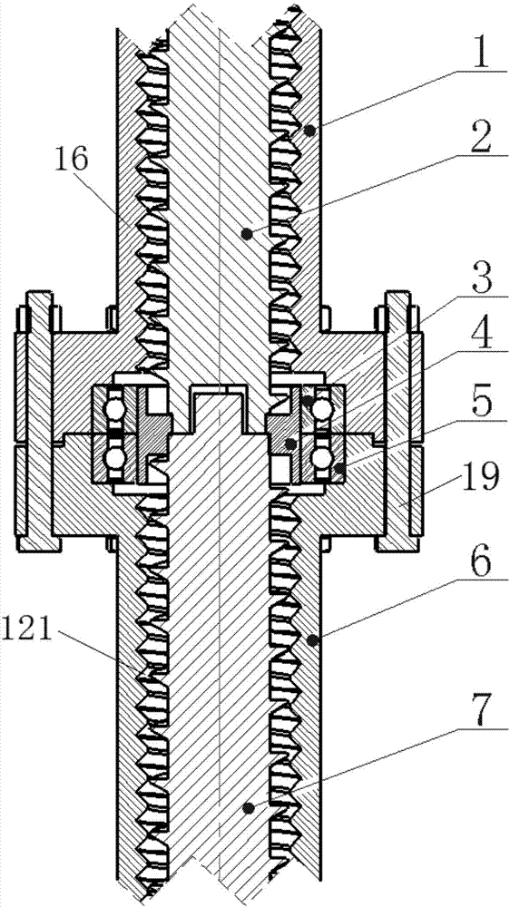
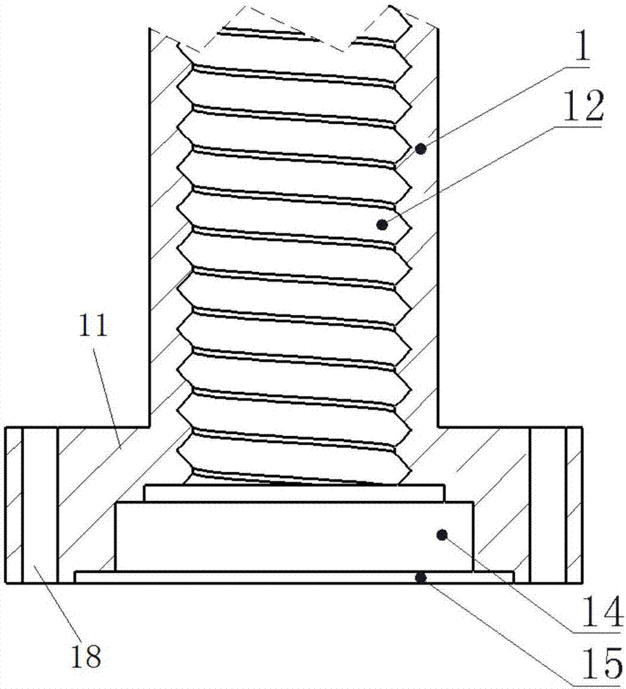
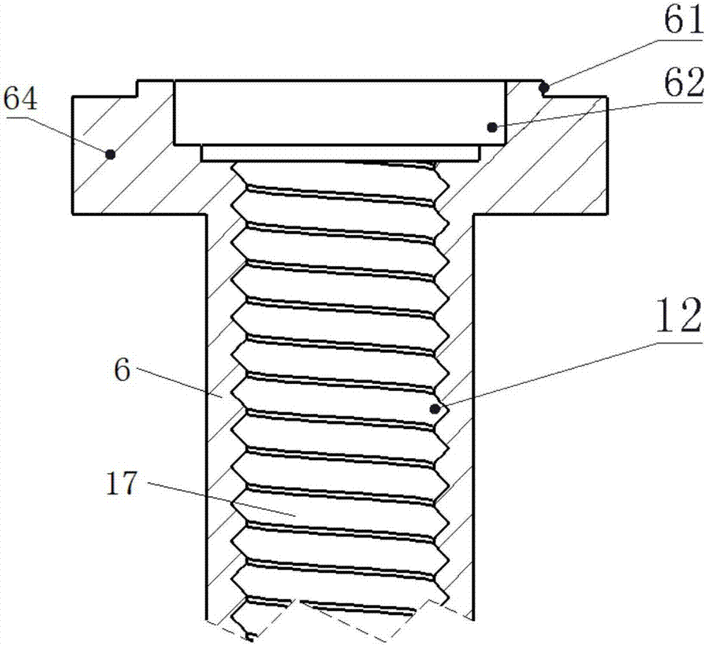
The invention provides a rock debris conveying device. The rock debris conveying device comprises a body with an axial cavity, a rotary part which is arranged in the axial cavity in a penetrating modeand is capable of rotating in the axial cavity, wherein the inner wall of the axial cavity is provided with a spiral groove; a spiral protrusion which can be embedded in the spiral groove is arrangedon the outer wall of the rotary part; the upper end face of the spiral protrusion is a plane; the lower end face of the spiral protrusion is a cambered face in smooth transition, and thus the lower end face of the spiral protrusion is attached to the inner wall of the spiral groove; and a gap allowing rock debris to pass through is formed between the upper end face of the spiral protrusion and the inner wall of the spiral groove. The rock debris conveying device can well convey rock debris out of a borehole.

Description

technical field [0001] The present application relates to the field of cuttings conveying, in particular to a cuttings conveying device. Background technique [0002] The descriptions in this section merely provide background information related to the disclosure in this application and may not constitute prior art. [0003] When drilling for oil, drilling mud is usually used to carry cuttings out of the wellbore. When there is no circulating mud and the water content of cuttings is uncertain, the effective transportation of cuttings becomes very difficult. The cuttings will enter the gap between the screw rod and the shell when the traditional screw is used to convey the cuttings, causing the screw rod to be stuck. [0004] It should be noted that the above introduction to the technical background is only for the convenience of a clear and complete description of the technical solution of the present application, and for the convenience of understanding by those skilled i...

Claims


Application Information

Patent Timeline
Patent Type & Authority Applications(China)
IPC IPC(8): B65G33/14B65G33/26
CPCB65G33/14B65G33/265B65G2201/045
Inventor 侯福祥王宏伟张全立唐纯静刘继亮
Owner BC P INC CHINA NAT PETROLEUM CORP
Learn More