Eureka AIR delivers breakthrough ideas for toughest innovation challenges, trusted by R&D personnel around the world.

Installing vehicle for large concrete components

A technology for concrete and installation vehicles, which is applied in the direction of transportation and packaging, trolley cranes, cranes, etc. It can solve the problems of low installation efficiency and incomplete guarantee of installation quality, so as to improve installation efficiency, facilitate on-site laying, and smooth installation process Effect

Inactive Publication Date: 2018-05-01
周瑞华
View PDF0 Cites 2 Cited by
  • Summary
  • Abstract
  • Description
  • Claims
  • Application Information

AI Technical Summary

Problems solved by technology

[0002] In the prior art, when installing large concrete components (comprehensive pipe gallery), most of the components are hoisted to the site by a crane, and the site installation is completely performed by manpower, the installation efficiency is low, and the quality of the site installation cannot be fully guaranteed

Method used


Image

  • Installing vehicle for large concrete components
  • Installing vehicle for large concrete components
  • Installing vehicle for large concrete components

Examples


Embodiment Construction

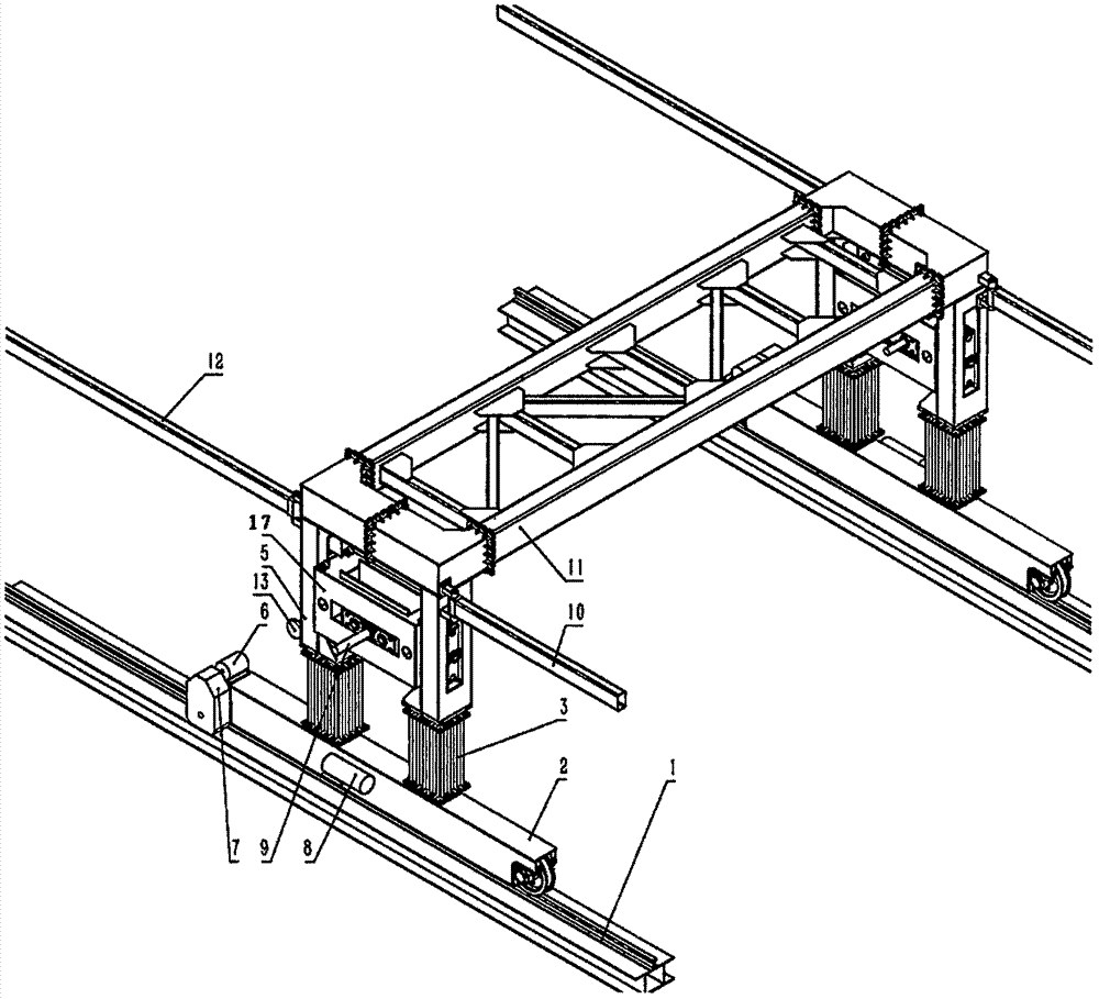
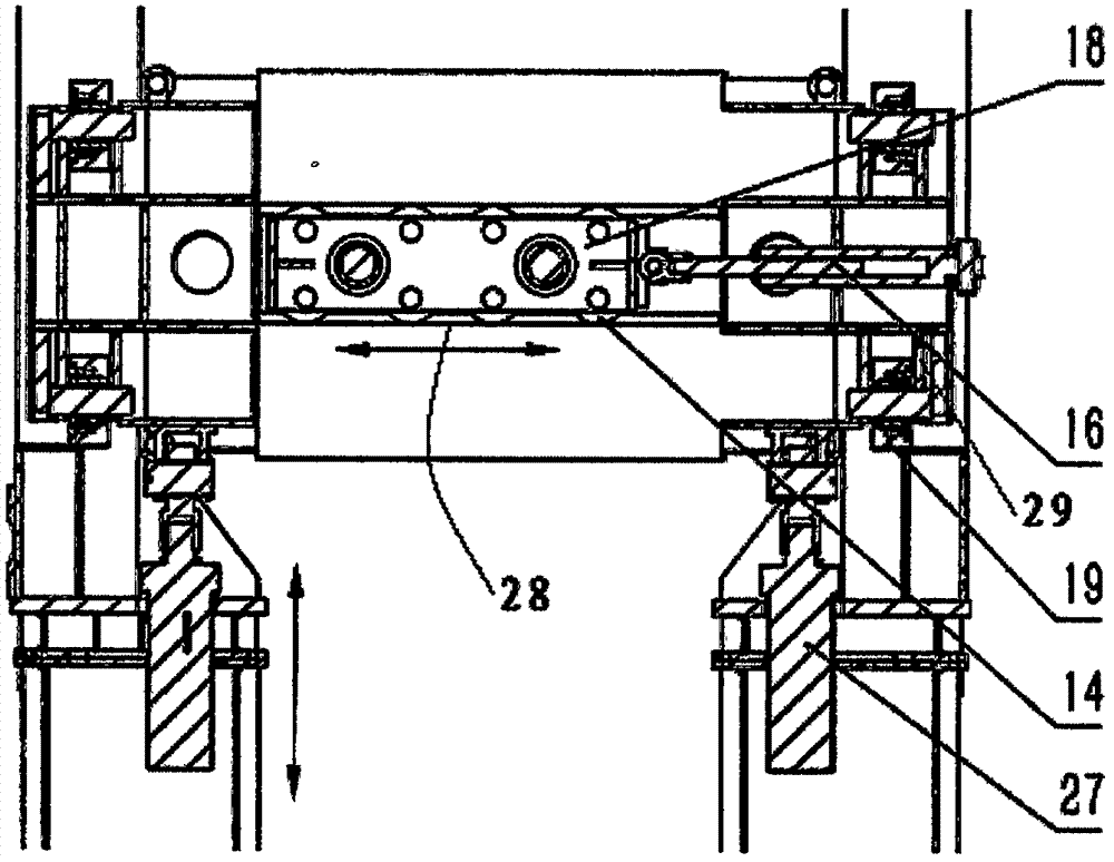
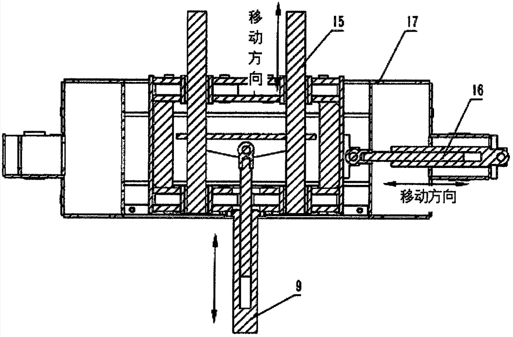
[0030] like figure 1 As shown, there is a door-shaped walking frame and a walking track 1, and the walking frame can move longitudinally on the walking track 1; the walking frame is composed of a transverse frame 11 and a leg 5, and the leg 5 is located below the transverse frame 11. Four outriggers are arranged below the horizontal support, and the four outriggers are arranged laterally and symmetrically in pairs. like figure 1 , figure 2 , image 3 As shown, a hydraulic three-dimensional adjustment device is provided at the corresponding outrigger position of the traveling frame, and two hydraulic three-dimensional adjustment devices are provided, and each hydraulic three-dimensional adjustment device is located between two outriggers on the same side in the Y direction. The hydraulic three-dimensional adjustment device includes a telescopic pin 15 , a first hydraulic cylinder 9 , a second hydraulic cylinder 16 , and a third hydraulic cylinder 27 . The telescopic pin sh...


PUM


Abstract

The invention relates to an installing vehicle for large concrete components. The installing vehicle is provided with an n-shaped walking frame and a walking track, and the walking frame can longitudinally move on the walking track. The installing vehicle is characterized in that the positions, corresponding to landing legs, of the walking frame are provided with hydraulic three-dimensional adjusting devices; and each hydraulic three-dimensional adjusting device comprises a telescopic pin shaft, a first hydraulic cylinder, a second hydraulic cylinder and a third hydraulic cylinder, wherein thetelescopic pin shaft is transversely arranged on a hydraulic adjusting device body and can transversely move relative to the hydraulic adjusting device body, the first hydraulic cylinder is transversely arranged and arranged in the X direction, a cylinder rod of the first hydraulic cylinder is connected with the telescopic pin shaft for driving of the telescopic pin shaft to transversely move, the second hydraulic cylinder is longitudinally arranged and arranged in the Y direction, a cylinder rod of the second hydraulic cylinder is connected with the hydraulic adjusting device body for driving of the hydraulic adjusting device body to longitudinally move, and the third hydraulic cylinder is vertically arranged and arranged in the Z direction, and the third hydraulic cylinder is used for driving the hydraulic adjusting device body to move up and down.

Description

technical field [0001] The invention relates to an installation vehicle for large concrete elements. Background technique [0002] In the prior art, when installing large concrete components (comprehensive pipe gallery), most of the components are hoisted to the site by a crane, and the site installation is completely performed by manpower. The installation efficiency is low, and the quality of the site installation cannot be fully guaranteed. Contents of the invention [0003] The object of the present invention is to provide an installation vehicle for large concrete components, which can effectively improve the installation efficiency and ensure the installation quality. [0004] The technical scheme that realizes the object of the present invention: [0005] An installation vehicle for large concrete components, with a door-shaped walking frame and a walking track, the walking frame can move longitudinally on the walking track; the walking frame is composed of a horiz...

Claims


Application Information

Patent Timeline
IPC IPC(8): B66C19/00
CPCB66C19/00
Inventor 周瑞华
Owner 周瑞华
Why Eureka
Eureka Blog
Learn More