
High precision positioning and orientation receiver

A high-precision technology for positioning and orientation, which is applied to satellite radio beacon positioning systems, instruments, and measuring devices. Disassemble the combination, save time and energy, and facilitate the effect of fixing on the ground

Active Publication Date: 2021-06-08
CHONGQING AOBIN SCI & TECH CO LTD
View PDF12 Cites 0 Cited by
  • Summary
  • Abstract
  • Description
  • Claims
  • Application Information

AI Technical Summary

Problems solved by technology

[0006] The purpose of the present invention is to solve the problem that the structure of the directional receiver in the prior art is too simple, it is not convenient to be installed on the ground as required, it is not convenient to be folded and stored and carried, the heat dissipation effect is poor, and the heat dissipation frame is not easy to disassemble and clean. High precision positioning and orientation receiver

Method used


Image

  • High precision positioning and orientation receiver
  • High precision positioning and orientation receiver
  • High precision positioning and orientation receiver

Examples


Embodiment Construction

[0023] The following will clearly and completely describe the technical solutions in the embodiments of the present invention with reference to the accompanying drawings in the embodiments of the present invention. Obviously, the described embodiments are only some, not all, embodiments of the present invention.

[0024] In describing the present invention, it should be understood that the terms "upper", "lower", "front", "rear", "left", "right", "top", "bottom", "inner", " The orientation or positional relationship indicated by "outside", etc. is based on the orientation or positional relationship shown in the drawings, and is only for the convenience of describing the present invention and simplifying the description, rather than indicating or implying that the referred device or element must have a specific orientation, so as to Specific orientation configurations and operations, therefore, are not to be construed as limitations on the invention.

[0025] In the present inv...


PUM


Abstract

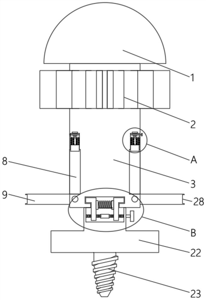
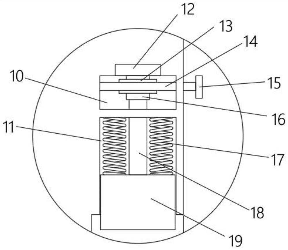
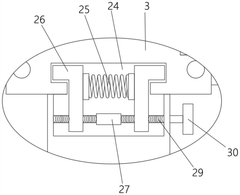
The invention discloses a high-precision positioning and directional receiver, which includes a bottom plate, a signal terminal and a body made of an integral molding mechanism, the body is covered with a heat dissipation frame, and a plurality of heat dissipation fins are equidistantly engaged on the heat dissipation frame Two nuts are symmetrically installed on the heat sink, each of the nuts is screwed with a bolt, and the part of the bolt located in the heat sink is rotatably connected with a first block with an arc-shaped structure. The heat dissipation frame is fixed on the body through the first block, and two storage slots are symmetrically opened on the body, and a pedal is connected to the bottom inner wall of each storage slot, and a second inner wall is provided on the upper end inner wall of the storage slot. A cavity. The invention has the advantages of stable structure, simple operation, scientific and reasonable design, short production period, low production cost, good heat dissipation performance, easy disassembly and assembly, and convenient fixing on the ground, which can save a lot of time and energy of workers, and is worthy of popularization.

Description

technical field [0001] The invention relates to the technical field of directional receivers, in particular to high-precision positioning and directional receivers. Background technique [0002] According to the continuous development of national science and technology, however, positioning technology is developing rapidly and the application area is getting wider and wider. Many different countries are constantly updating and developing positioning and directional receivers with different requirements and some large-scale data processing software. By using the antenna The corresponding current is converted by the receiver and the preamplifier, which can better continuously amplify the signal current of the well-known domestic positioning and directional receiver. [0003] When using pseudo-range for satellite positioning, whether it is single-point positioning (SPP) or pseudo-range differential positioning (DGPS), usually the positioning accuracy can only reach the sub-mete...

Claims


Application Information

Patent Timeline
Patent Type & Authority Patents(China)
IPC IPC(8): G01S19/13
CPCG01S19/13
Inventor 潘晓林
Owner CHONGQING AOBIN SCI & TECH CO LTD
Learn More