

Dynamic power network topology modeling method and system
A technology of power network and modeling method, applied in the direction of AC network circuits, electrical components, circuit devices, etc., to achieve the effect of improving functions and performance, and improving modeling speed
- Summary
- Abstract
- Description
- Claims
- Application Information
AI Technical Summary
Problems solved by technology
Method used
Image

Examples
Embodiment 1
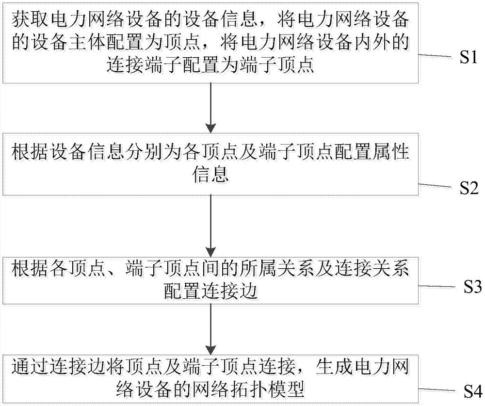
[0039] An embodiment of the present invention provides a dynamic power network topology modeling method, such as figure 1 As shown, the power network topology modeling method includes:
[0040] Step S1: Obtain the device information of the power network device, configure the device body of the power network device as a vertex, and configure the connection terminals inside and outside the power network device as a terminal vertex.
[0041] Step S2: Configure attribute information for each vertex and terminal vertex according to the equipment information.
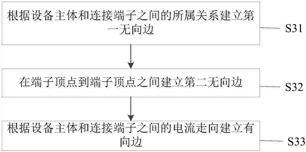
[0042] Step S3: Arranging connection edges according to the belonging relationship and connection relationship between vertices and terminal vertices.
[0043]Step S4: Connect the vertices and terminal vertices by connecting edges to generate a network topology model of the power network equipment.
[0044] The dynamic power network topology modeling method provided by the embodiment of the present invention realizes the mo...
Embodiment 2
[0062] An embodiment of the present invention provides a dynamic power network topology modeling system, such as Figure 7 As shown, it includes: initialization module 1, which obtains the device information of the power network device, configures the device body of the power network device as a vertex, and configures the connection terminals inside and outside the power network device as a terminal vertex; attribute information configuration module 2, according to the device information Configure attribute information for each vertex and terminal vertex respectively; connection edge configuration module 3 configures connection edges according to the ownership relationship and connection relationship between each vertex and terminal vertex; network topology model construction module 4 connects vertices and terminal vertices through connection edges , to generate a network topology model of power network equipment.
[0063] The dynamic power network topology modeling system pro...
Embodiment 3
[0071] An embodiment of the present invention provides a non-transitory computer storage medium, the computer storage medium stores computer-executable instructions, and the computer-executable instructions can execute the dynamic power network topology modeling method in Embodiment 1 above. Wherein, the above-mentioned storage medium may be a magnetic disk, an optical disk, a read-only memory (Read-Only Memory, ROM), a random access memory (Random Access Memory, RAM), a flash memory (Flash Memory), a hard disk (Hard Disk Drive, abbreviation: HDD) or a solid-state drive (Solid-State Drive, SSD), etc.; the storage medium may also include a combination of the above types of memories.
[0072] Those skilled in the art can understand that all or part of the processes in the methods of the above-mentioned embodiments can be completed by instructing related hardware through computer programs, and the programs can be stored in a computer-readable storage medium. , may include the flo...
PUM
 Abstract
Description
Claims
Application Information