Self-aligning wireless charging system

A wireless charging and self-aligning technology, used in charging stations, electric vehicle charging technology, electric vehicles, etc., can solve the problems of reducing wireless charging efficiency and speed, affecting charging efficiency, and low coupling coefficient.

Pending Publication Date: 2018-05-04
江苏傲能科技有限公司
View PDF7 Cites 6 Cited by
  • Summary
  • Abstract
  • Description
  • Claims
  • Application Information

AI Technical Summary

Problems solved by technology

The deviation of the parking position of the electric vehicle may cause a certain misalignment between the receiving coil and the transmitting coil, which will affect the operation of the entire system, reduce the charging efficiency and increase the charging time.
[0003] In addition, for the existing planar structure induction coil, the structure of the single clockwise winding method is very simple, but the problem of the planar structure coil is that there is a large gap between the adjacent transmitting coil and receiving coil. When charging, the part of the magnetic force line between the transmitting coil and the receiving coil in the gap cannot be coupled for charging, resulting in the waste of the magnetic force line part between the transmitting coil and the receiving coil in the gap, which reduces the efficiency and speed of wireless charging. The induction coil with such a planar structure has a low coupling coefficient between the transmitting and receiving coils per unit area due to its planar structure, which directly affects the charging efficiency, especially in high-power wireless charging, where the loss is particularly serious
[0004] Therefore, the development of a wireless charging technology with an automatic alignment device can avoid the problem that the magnetic flux part between the transmitting coil and the receiving coil in the gap in the prior art is wasted in vain and reduces the efficiency and speed of wireless charging. Charging is important

Method used


Image

  • Self-aligning wireless charging system
  • Self-aligning wireless charging system
  • Self-aligning wireless charging system

Examples


Embodiment Construction

[0032] The present invention will be further described below in conjunction with the accompanying drawings and embodiments.

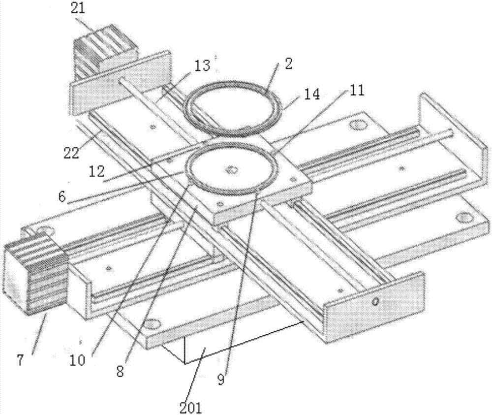
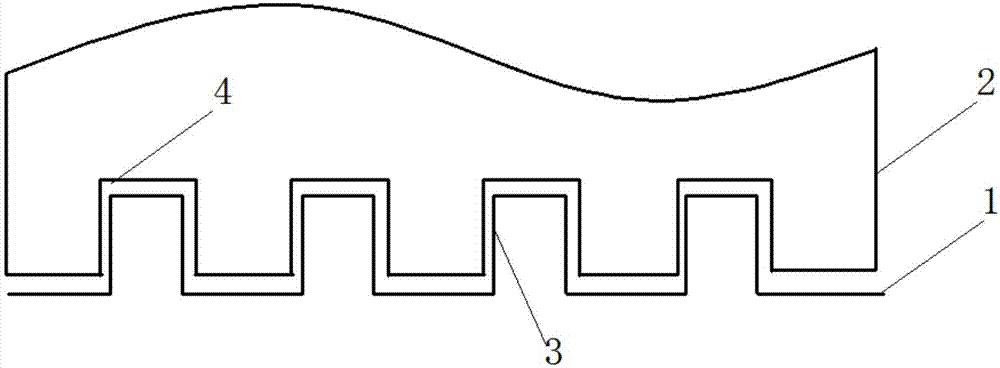
[0033] According to attached Figure 1-Figure 7 It can be seen that the self-aligned wireless charging system of this embodiment includes a transmitting coil 1 and a receiving coil 2, and the transmitting coil 1 and receiving coil 2 are both hollow coils;

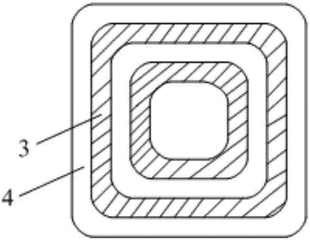
[0034] The top wall of the transmitting coil 1 is provided with a protrusion 3 formed by a coil winding;

[0035] A coil winding is also arranged on the bottom wall of the receiving coil 2, and the inside of the coil winding forms a groove 4;

[0036] There are several protrusions 3 and several grooves 4, the number of the protrusions 3 is the same as that of the grooves 4, and the protrusions 3 correspond to the grooves 4 one by one;

[0037] Each of the protrusions 3 can extend into its corresponding groove 4 and the outer wall of the protrusion 3 fits the inner wall of the groove 4;

[0038] Un...


PUM


Abstract

The invention provides a self-aligning wireless charging system. Under the condition that a transmitting coil directly faces a receiving coil, each protrusion directly faces a groove corresponding tothe protrusion; the receiving coil is arranged on a chassis of an electric car, a ring-shaped reflector of sensors is placed on the outer side of the receiving coil and used for reflecting optical signals sent out by the sensors, the transmitting coil is arranged on a cross-shaped sliding table, and the cross-shaped sliding table can be used for X-direction and Y-direction mixing movement; the four sensors are arranged on the transmitting coil; the four sensors are located on the outer sides of the points where the transmitting coil is crossed with the X-axis direction and the Y-axis direction; the bottom of the cross-shaped sliding table is connected with the upper surface of a lifting platform which is installed on the ground of a parking lot, and the cross-shaped sliding table can be driven by a driving motor to go up and down. By means of the self-aligning wireless charging system, the defects in the prior art that the magnetic line parts of the transmitting coil and the receivingcoil at a gap are lost in vain, so that the wireless charging efficiency and speed are reduced, and the transmitting coil and the receiving coil are not aligned to a device.

Description

technical field [0001] The invention relates to the technical field of wireless charging, in particular to a self-aligned wireless charging system. Background technique [0002] The power transmission efficiency of both the magnetic induction type and the magnetic resonance type is related to the coupling coefficient between the two parallel coils of the transmitting coil and the receiving coil. And when the shape and size of the coil are determined, when the two parallel coils have the largest facing area, the coupling coefficient is also the largest, and the transmission efficiency is also the highest. The deviation of the parking position of the electric vehicle may cause a certain misalignment between the receiving coil and the transmitting coil, which will affect the working condition of the entire system, reduce the charging efficiency and increase the charging time. [0003] In addition, for the existing planar structure induction coil, the structure of the single cl...

Claims


Application Information

Patent Timeline
Patent Type & Authority Applications(China)
IPC IPC(8): B60L11/18
CPCB60L53/12B60L53/38Y02T10/70Y02T90/12Y02T10/7072Y02T90/14
Inventor 周小舟徐维彭燕昌周宁宁
Owner 江苏傲能科技有限公司
Why Eureka
Try Eureka