Eureka AIR delivers breakthrough ideas for toughest innovation challenges, trusted by R&D personnel around the world.

Instrument panel beam installing structure

An installation structure and instrument panel technology, which is applied in the field of auto parts, can solve problems such as poor stiffness and mode of the installation structure of the instrument panel beam, resonance of the instrument panel and steering wheel, and poor torsional stiffness of the vehicle, so as to optimize the installation structure mode, Simplification of parts and processes, reduction of plate thickness to achieve the effect

Pending Publication Date: 2018-05-04
SAIC-GM-WULING AUTOMOBILE CO LTD
View PDF6 Cites 1 Cited by
  • Summary
  • Abstract
  • Description
  • Claims
  • Application Information

AI Technical Summary

Problems solved by technology

[0004] 1. The Y-direction installation point needs to be assembled through the cavity of the side wall assembly, which hinders the operation line of sight, increases the difficulty of assembly, and affects the assembly cycle;
[0005] 2. There are 3 mounting bolts on one side, the number is large, which affects the assembly speed; in addition, the Y-direction mounting point has installation holes for instrument panel beam bolts on the side wall outer panel, and sealant plugs are required;
[0006] 3. The rigidity and modality of the instrument panel beam installation structure are poor, and the front side panel and the instrument panel beam mounting bracket for improved installation are usually thicker (the thickness of the mounting bracket is t=1.5mm, and the front side panel is t=1.2mm). Provide cavity structure to ensure installation;
[0007] 4. The X-direction assembly method causes the instrument panel beam and the mounting bracket on the vehicle body to be welded only half a circle, and the connection strength is not good. The instrument panel beam with this structure has a low modality, which is likely to cause resonance of the instrument panel and steering wheel, and the driving experience Difference
[0008] 5. The poor connection between the instrument panel beam and the left and right side walls leads to poor torsional rigidity of the vehicle

Method used


Image

  • Instrument panel beam installing structure
  • Instrument panel beam installing structure
  • Instrument panel beam installing structure

Examples


Embodiment Construction

[0042] The specific embodiments of the present invention are given below in conjunction with the accompanying drawings, but the present invention is not limited to the following embodiments. Advantages and features of the present invention will be apparent from the following description and claims. It should be noted that all the drawings are in very simplified form and use imprecise ratios, which are only used for the purpose of conveniently and clearly assisting in describing the embodiments of the present invention.

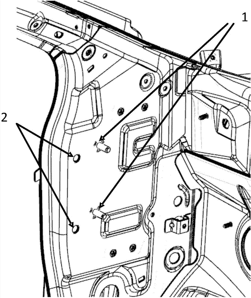
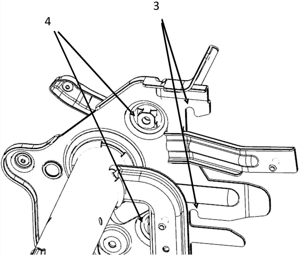
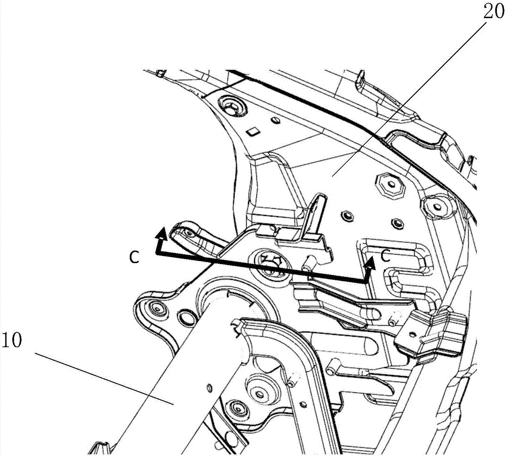
[0043] Please refer to Figure 1 ~ Figure 4 , figure 1 Shown is a schematic diagram of the side wall outer panel structure of a preferred embodiment of the present invention, figure 2 Shown is a schematic diagram of the instrument panel beam structure of a preferred embodiment of the present invention, image 3 Shown is a schematic diagram of the structure of the instrument panel beam fixed on the side wall outer panel in a preferred embodiment of the pres...


PUM


Abstract

The invention provides an instrument panel beam installing structure which comprises an instrument panel beam and a side outer plate; the instrument panel beam comprises U-shaped positioning structures, the side outer plate comprises a positioning bolt, the U-shaped positioning structure is hooked into the positioning bolt and used for limiting movement of the instrument panel beam, wherein a guiding support is further arranged on the side outer plate and used for fixing the instrument panel beam to the side outer plate through an installing bolt. Furthermore, one side of the instrument panelbeam is provided with two U-shaped positioning structures, the side outer plate is provided with two positioning bolts to be matched with the U-shaped positioning structures. According to the instrument panel beam installing structure, the technology and parts are simplified, the rigidity of an installing point is optimized, the car body connection strength is improved, and the light weight of thestructure is achieved.

Description

technical field [0001] The invention relates to the field of auto parts, and in particular to an instrument panel beam installation structure. Background technique [0002] The installation structure of the instrument panel beam is an extremely important installation structure of the car body. The stiffness of the installation point affects the mode of the instrument panel beam, which is directly related to the vibration degree of the steering wheel under various working conditions, and at the same time affects the comfort and operability of the driver. The instrument panel beam is not only used to install the instrument panel, steering wheel and other parts, but also a key beam connecting the left and right side walls. The strength of the mounting points on the left and right sides affects the torsional stiffness of the vehicle. The traditional instrument panel beam installation structure usually has three installation points on one side, two of which are directly assembled...

Claims


Application Information

Patent Timeline
Patent Type & Authority Applications(China)
IPC IPC(8): B62D25/14B62D27/02
CPCB62D25/145B62D27/02
Inventor 覃鹏飞陈建军伍升安刘亚陈聪许冰谢贵山
Owner SAIC-GM-WULING AUTOMOBILE CO LTD
Why Eureka
Eureka Blog
Learn More