Vacuum chamber

A vacuum box and box technology, which is applied in object supply, pile separation, thin material processing, etc., can solve the problem that the vacuum adsorption range cannot be adjusted, and achieve the effect of improving the actual vacuuming efficiency

Pending Publication Date: 2018-05-04
GUANGDONG DONGFANG PRECISION SCI & TECH CO LTD
View PDF7 Cites 0 Cited by
  • Summary
  • Abstract
  • Description
  • Claims
  • Application Information

AI Technical Summary

Problems solved by technology

[0004] In view of the shortcomings of the prior art above, the purpose of the present invention is to provide a vacuum box, aiming to solve the technical problem that the vacuum adsorption range of the corrugated cardboard dryer cannot be adjusted in the prior art

Method used


Image

  • Vacuum chamber
  • Vacuum chamber
  • Vacuum chamber

Examples


Embodiment Construction

[0021] The present invention provides a vacuum box. In order to make the purpose, technical solution and effect of the present invention clearer and clearer, the present invention will be further described in detail below with reference to the accompanying drawings and examples. It should be understood that the specific embodiments described here are only used to explain the present invention, not to limit the present invention.

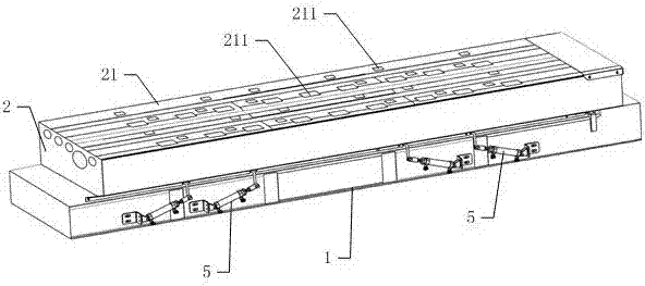
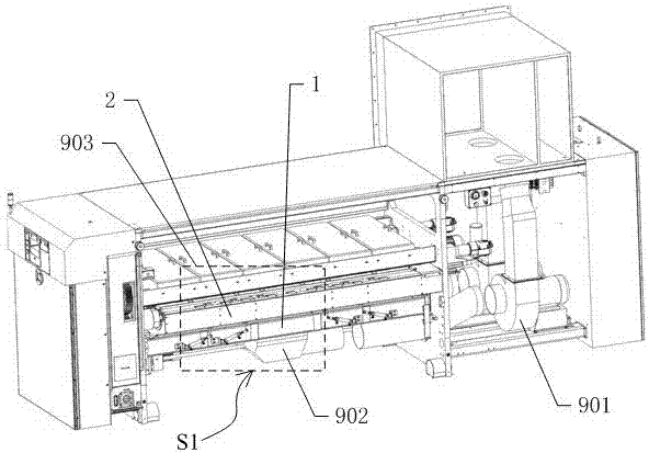
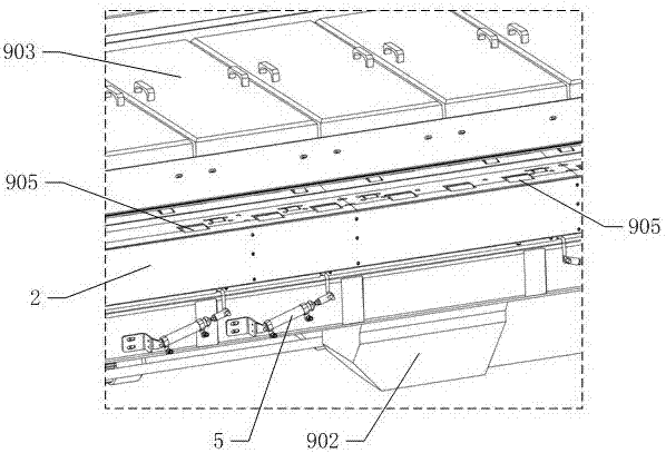
[0022] see Figure 1 to Figure 6 , The invention provides a vacuum box. In order to facilitate understanding of the technical scheme of the present invention, figure 2 and Figure 4 The drying machine that has applied the vacuum box that the present invention provides in is shown; For the convenience of observing the internal structure of vacuum box, Figure 4 and Figure 5 Neither shows the side panel of the vacuum chamber facing the viewer.

[0023] The vacuum box includes a base 1 and a box body 2 arranged on the base. The top plate 21 of th...


PUM


Abstract

The invention discloses a vacuum chamber which comprises a base and a box arranged on the base. A plurality of paper feeding wheel holes are formed in a top plate of the box, an air flue is arranged on the base, and the air flue and the multiple paper feeding wheel holes are communicated with an inner cavity of the box; a plurality of vertical separating plates are arranged in the inner cavity ofthe box, each vertical separating plate is provided with an air opening, an air door plate is rotationally connected to the air opening of each vertical separating plate, and each air door plate is connected with a driving device used for rotating the air door plate. By means of the vacuum chamber, the vacuum adsorption zone at the top of the box can be adjusted, and the vacuum chamber is suitablefor conveying corrugated boards in different sizes.

Description

technical field [0001] The invention relates to the technical field of printing machinery and equipment, in particular to a vacuum box. Background technique [0002] The corrugated cardboard needs to be dried after printing, that is, the ink printed on the corrugated cardboard is dried quickly by means of hot air or infrared heating. The patent with the authorized notification number CN 203567342U discloses a double-group drying device for a carton printing machine, which discloses a technical solution in which the vacuum equipment is connected to the transmission box and sucks the air in the transmission box. However, there are still the following deficiencies: The vacuum adsorption range on the upper surface of the transmission box cannot be adjusted. When the size of the corrugated cardboard cannot cover the upper surface of the transmission box, "air leakage" will occur at the transmission wheel not covered by the corrugated cardboard, making vacuum equipment (such as: e...

Claims


Application Information

Patent Timeline
Patent Type & Authority Applications(China)
IPC IPC(8): B65H5/22
CPCB65H5/222B65H2406/366B65H2701/176
Inventor 唐灼林毛兴洪
Owner GUANGDONG DONGFANG PRECISION SCI & TECH CO LTD
Why Eureka
Try Eureka