
A dynamic self-balancing structure

A self-balancing and dynamic technology, applied in the field of dynamic self-balancing structures, based on MEMS double-ended fixed-supported suspension beams, can solve the problems of precision constraints, high cost, and high process requirements, and achieve dynamic control and convenient production , easy-to-make effects

Active Publication Date: 2019-06-11
YANGZHOU UNIV
View PDF4 Cites 0 Cited by
  • Summary
  • Abstract
  • Description
  • Claims
  • Application Information

AI Technical Summary

Problems solved by technology

The rotating gyro shaft always tries to point to a fixed direction. If two gyroscopes whose rotation axes are at right angles to each other form a platform and place the platform in the gimbal, the platform will remain stable no matter how the gimbal rotates. In this way, an inertial navigation system is formed, which is also the balance principle of a self-balancing car. However, the mechanical gyro has a complex structure and high process requirements. Its accuracy is restricted by many factors and the cost is relatively high.

Method used


Image

  • A dynamic self-balancing structure
  • A dynamic self-balancing structure
  • A dynamic self-balancing structure

Examples


Embodiment Construction

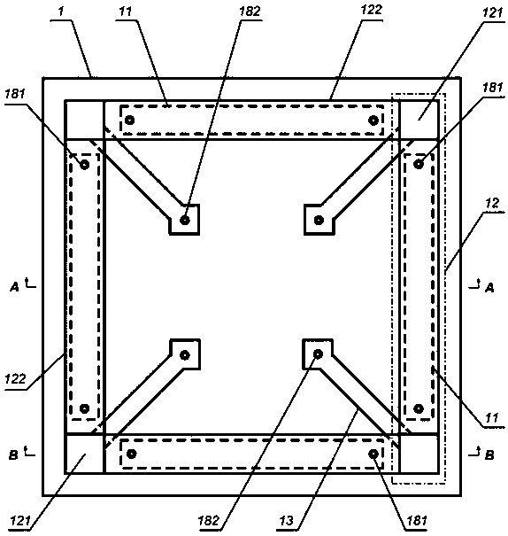
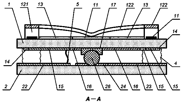
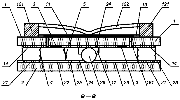
[0028] Such as figure 1 As shown in -7, the dynamic self-balancing structure includes an upper substrate 1, and four resistance strips 11, four double-terminal fixed support suspension electrodes 12 and four ground electrodes 13 on the top surface of the upper substrate are arranged on the top surface of the upper substrate 1; The bottom surface of the upper substrate 1 is provided with four pull-down electrodes, upper electrodes 14, four voltage dividing resistors 3, an annular DC bias electrode 15 and an annular ground electrode 16 on the bottom surface of the upper substrate, and the spherical hinge hemisphere is fixedly connected to the center of the bottom surface of the upper substrate 1. Shaped base 17 , a plurality of DC bias metal vias 181 and a plurality of ground metal vias 182 penetrating through the upper substrate 1 are provided on the upper substrate 1 .

[0029]Two of the four resistance strips 11 on the top surface of the upper substrate 1 are arranged horizon...


PUM


Abstract

A dynamic self-balancing structure belongs to the technical field of automatic control based on micro-electromechanical systems (MEMS), comprising an upper substrate, and four resistance bars, four double-ended fixed suspension electrodes and four upper substrates are arranged on the top surface of the upper substrate Top surface grounding electrode; four pull-down electrodes, four voltage dividing resistors, annular DC bias electrodes and annular grounding electrodes on the bottom surface of the upper substrate are arranged on the bottom surface of the upper substrate, and a spherical hinge hemispherical base is fixedly connected to the center of the bottom surface of the upper substrate A DC bias metal through hole and a grounding metal through hole are arranged on the upper substrate; a lower substrate is arranged below the upper substrate, and four pull-down electrodes, a lower electrode, a DC bias input electrode, and a DC ground electrode are arranged on the top surface of the lower substrate. . The annular ground electrode on the top surface of the lower base plate and the ground electrode are connected with wires, and the spherical hinge spherical body is fixedly connected on the lower base plate. The invention perceives and adjusts the deviation of the plane where the structure is located relative to the horizontal plane in real time, so as to realize the dynamic self-balancing of the structure.

Description

technical field [0001] The invention relates to a dynamic self-balancing structure and method, in particular to a dynamic self-balancing structure and method based on MEMS double-end fixed-supported suspension beams, and belongs to the technical field of automatic control based on micro-electromechanical systems (MEMS). Background technique [0002] As large as airplanes and ships, as small as balance cars and mobile phones, during their operation, the body will tilt or the orientation will be deflected due to various factors, which will affect their operating status, and corresponding measures need to be taken to maintain their operation Dynamic balance in the process. [0003] The devices used to detect and control the balance state of moving objects in the prior art are mainly gyroscopes. Traditional inertial gyroscopes are mainly mechanical gyroscopes, of which liquid floating gyroscopes, dynamic gyroscopes and electrostatic gyroscopes are typical structures. The rotati...

Claims


Application Information

Patent Timeline
Patent Type & Authority Patents(China)
IPC IPC(8): G01C19/56B81B3/00
CPCB81B3/0027B81B2203/05
Inventor 赵成陈磊张凯杨义军胡经国
Owner YANGZHOU UNIV
Learn More